Contents
Redundancy and fault tolerance
Fault tolerance ensures continuous and uninterrupted transmission of traffic over the SD-WAN network and functioning of network services. Fault tolerance is enhanced by the use of redundancy and failover mechanisms at different levels of the network infrastructure, for example, you can create backup service interfaces.
A fault-tolerant network can remain operational in case of minor problems as well as major disasters involving central components such as routers, links, and data centers. When a component fails, a backup component of the same type takes its place. For example, you can create a backup link to which traffic is transferred if the main link becomes unavailable.
Fault tolerance makes it easier to balance the load across multiple links by optimizing the utilization of traffic bandwidth and avoiding congestion. This helps avoid any existing link becoming a bottleneck in the network topology.
Kaspersky SD-WAN maintains continuous operation in the event of the following types of faults:
- Failure of a central component, such as , SD-WAN Gateway, or
- Failure or overload of communication channels between geographically redundant central components, when network components are located at geographically dispersed locations to make data storage more reliable
- Failure or congestion of communication channels between and SD-WAN gateways
Redundancy of central components of the solution
Kaspersky SD-WAN supports two component deployment schemes: N+1 and 2N+1.
The N+1 deployment scheme means that one backup component is deployed alongside an active component. If the active component fails, the backup component instantly takes its place, ensuring continuity of operation.
The 2N+1 deployment scheme is an expanded version of N+1 and differs in that it has an additional level of redundancy. In this scheme, the active component consists of two sets. These are synchronized with each other, and one can take the place of the other if a malfunction occurs. One extra backup component is also deployed. This redundancy scheme allows components to remain operational even when multiple failures occur in a row.
The table below shows the redundancy schemes and protocols that are used for different components of the solution.
Redundancy schemes for components of the solution
Component |
Redundancy scheme |
Protocol used |
|---|---|---|
Orchestrator |
N+1 |
REST |
Orchestrator web interface |
N+1 |
REST |
Orchestrator database |
2N+1 |
MONGODB |
SD-WAN Controller and its database |
2N+1 |
OPENFLOW (TLS) |
SD-WAN Gateway |
N+1 |
GENEVE |
An example of locating solution components in geographically dispersed data centers is shown in the figure below. All subsequent figures use the same symbols:
- orchestrator — orc
- orchestrator web interface — www
- orchestrator database — orc-dbs
- SD-WAN Controller and its database — ctl
- SD-WAN gateway — GW
For components of the solution that are N+1 redundant, two nodes are deployed in separate data centers. Each of the nodes is in the active state. You can use a virtual IP address or DNS service to select the node to which requests are directed.
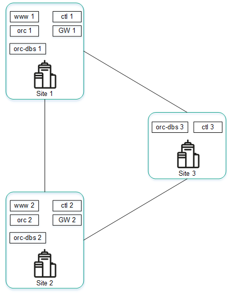
Placing solution components in geographically dispersed data centers
Components that are 2N+1 redundant form a cluster. This cluster contains one primary node and two nodes providing redundancy. You can designate one of the nodes as an arbiter to economize resources and reduce the requirements for the links.
If a cluster node is designated as an arbiter, it does not contain a database and you cannot make it the primary node. The arbiter node takes part in voting when the primary node is selected and exchanges periodic service packets (heartbeats) with other nodes.
The figure below shows an example of an failure at one of the locations and how the solution responds to it. This example shows an accident in which the nodes of the solution component cluster fail at location 1.
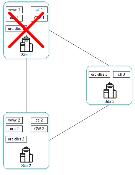
Accident at location 1
If nodes of the solution component cluster at location 1 fail, the following events occur:
- Node orc-dbs 2 and arbiter node orc-dbs 3 lose contact with node orc-dbs 1, and subsequently vote for a new primary node.
- Arbiter node orc-dbs 3 cannot be the primary node, therefore orc-dbs 2 becomes the primary node and informs the orchestrator of its role.
- Node ctl 2 and arbiter node ctl 3 lose contact with node ctl 1, and subsequently vote for a new primary node.
- Arbiter node ctl 3 cannot be the primary node, therefore ctl 2 becomes the primary node and informs the orchestrator of its role.
The figure below shows an accident in which the nodes of the solution component cluster fail at location 2.
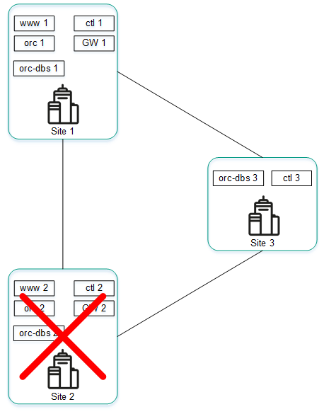
Accident at location 2
If nodes of the solution component cluster at location 2 fail, the following events occur:
- Node orc-dbs 1 and arbiter node orc-dbs 3 lose contact with node orc-dbs-2, after which node orc-dbs 1 remains the primary node.
- Node ctl 1 node and arbiter node ctl 3 lose contact with node ctl 2, after which node ctl 1 remains the primary node.
The figure below shows an example of an accident in which the connection between location 1 and location 2 is severed.
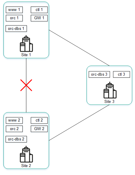
Connection failure between location 1 and location 2
If cluster nodes of solution components at location 1 and location 2 cannot connect to each other, the following events occur:
- Node orc-dbs 1 loses contact with node orc-dbs 2.
- Node orc-dbs 1 node remains the primary node because arbiter node orc-dbs 3 observes both locations operating normally.
- Node ctl 1 loses contact with node ctl 2.
- Node ctl 1 remains the primary node because arbiter node ctl 3 observes both locations operating normally.
The figure below shows an example of an accident in which the connection between location 1 and other locations is severed.
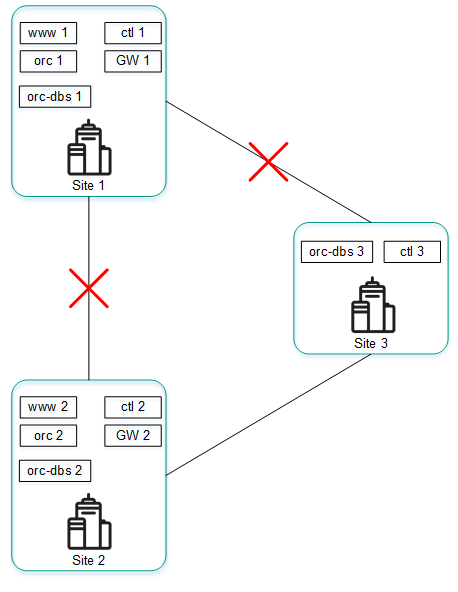
Failure of connections between location 1 and other locations
If cluster nodes of solution components at location 1 cannot connect to other locations, the following events occur:
- Node orc-dbs 1 loses contact with node orc-dbs 2.
- Node orc-dbs 2 becomes the primary node and informs the orchestrator of its role because the arbiter node orc-dbs 3 observes that location 1 is unavailable.
- Node ctl 1 loses contact with node ctl 2.
- Node ctl 2 becomes the primary node and informs the orchestrator of its role because arbiter node ctl 3 observes that location 1 is unavailable.
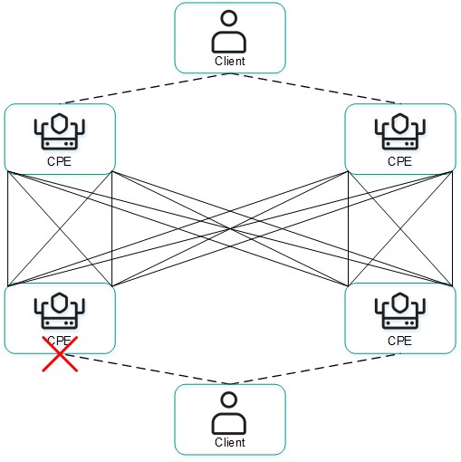
Redundancy of communication channels between CPE devices
Kaspersky SD-WAN guards against interruptions in communication between CPE devices by simultaneously using all available communication channels, for example, Internet or LTE channels.
Active/Active mode
In this mode, all WAN interfaces of CPE devices are in the active state and transmit user traffic.
The SD-WAN Controller balances traffic using 2 to 16 transport paths (multipathing). Balancing evenly distributes traffic among links, which prevents congestion of individual links and performance problems for users. Three balancing modes are supported:
- Per flow balancing, taking into account information at levels L2 to L4. In this mode, two types of balancing are available:
- Equal balancing — the streams are allocated evenly among paths.
- Unequal balancing — the streams are allocated among paths proportionally to the costs of the links.
- Per packet — packets are allocated in proportion to the cost of the links during transmission.
- Broadcast — packets are sent to all links simultaneously to prevent losses.
In Active/Active mode, the CPE device remains available as long as at least one communication channel is operational.
Active/Standby mode
In this mode, you must select the primary and reserve transport paths for the traffic. In this case, balancing is not used. Rules for using the reserve WAN interface in a situation when the path through the main WAN interface becomes unavailable are loaded to the CPE device in advance. In this case, if the main transport path is disrupted, packet switching rules are not rewritten, and the device sends the packets through the reserve interface.
You can configure redundancy at the transport service level. When creating the transport service, you specify reserve service interfaces (reserve SI) on the selected CPE device or on another device. We recommend creating the primary and reserve service interfaces on different devices. Traffic is switched to the reserve service interface if the primary SI is unavailable.
The solution supports creating reserve service interfaces for all types of L2 transport services.
The figures below show typical examples of communication interruptions between CPE devices:
- Failure of one of the CPE devices.
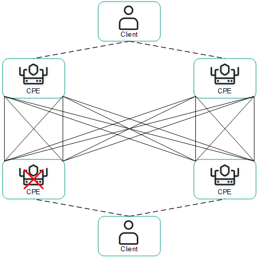
- Failure of a WAN interface of one of the CPE devices.
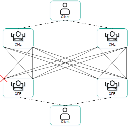
- Loss of connectivity between two CPE devices.
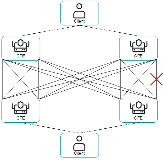
- Failure of a LAN interface of one of the CPE devices.