Contents
Configuring topology
Links form a topology that determines the connectivity of devices in the data plane and is responsible for optimizing the passage of traffic of transport services. In Kaspersky SD-WAN, devices can be arranged in one of the following topologies:
- Hub-and-Spoke is the default topology in which links between CPE devices are established through the SD-WAN Gateway.
- Full-Mesh is a topology in which direct links are created between all CPE devices.
- Partial-Mesh is a topology in which direct links are established between some of the CPE devices.
A role is assigned to each CPE device: standard device or SD-WAN Gateway. Standard devices automatically establish links with SD-WAN Gateways, which in turn establish links with all devices on the network, including other gateways. By default, all devices are standard devices. The SD-WAN Gateway role is required to build a Hub-and-Spoke topology.
Standard devices can be assigned topology tags to make them transit devices. If two devices are assigned the same topology tag, a link is automatically created between them. Other devices establish links through transit devices. Topology tags and transit devices are used to build Full-Mesh and Partial-Mesh topologies.
In addition to topology tags, the solution also uses standard tags that allow you to classify CPE devices by various criteria, such as model, software version, or street address of the location, and perform group actions on the devices, such as firmware updates. Topology tags and standard tags are not related to each other in any way.
About the Hub-and-Spoke topology
The Hub-and-Spoke topology is a network architecture in which a hub site is connected to multiple spoke sites for the purposes of exchanging traffic. This topology is the most common for SD-WAN network design because it simplifies network management and provides a higher level of security by routing traffic through the hub site where traffic analysis and categorization is performed. The Hub-and-Spoke topology also enables more efficient use of bandwidth by optimizing and prioritizing traffic at the hub site.
This section describes examples of such topologies that you can build using Kaspersky SD-WAN. Note that when building a Hub-and-Spoke topology, you can use QoS to limit the bandwidth available to CPE devices or specific traffic classes.
Hub-and-Spoke without connection between remote offices
The figure below shows a topology in which remote locations are connected to the central office and cannot directly communicate with each other. SD-WAN networks built using this topology are easy to design and maintain, because all necessary network services and applications are located in the central data center.
CPE devices registering with the orchestrator are automatically included in the management transport service with the Leaf role and can be behind NAT (Network Address Translation) and PAT (Port Address Translation). In this topology, direct exchange of traffic between devices is not possible.
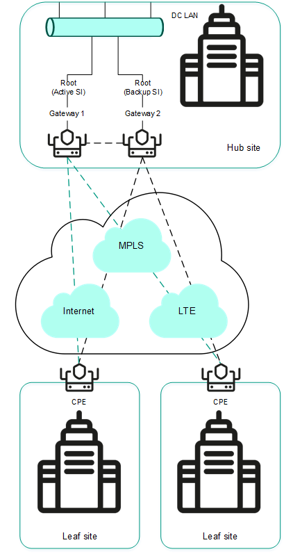
Hub-and-Spoke topology without connection between remote offices
Hub-and-Spoke topology with connection between remote offices through the central office
The figure below shows a topology in which remote locations can communicate with each other through the central office. CPE devices registering with the orchestrator are automatically included in the transport service and can be behind NAT and PAT.

Hub-and-Spoke topology with connection between remote offices through the central office
Page topAbout Full-Mesh and Partial-Mesh topologies
Kaspersky SD-WAN supports Full-Mesh and Partial-Mesh topologies. To implement these topologies, the network administrator must grant permission to dynamically create direct links between CPE devices.
Creating direct links between CPE devices improves the performance of Kaspersky SD-WAN thanks to the following:
- Improved qualitative characteristics of the physical communication channel between CPE devices, such as delay, loss, and jitter, compared to the CPE1 → gateway → CPE2 transit scenario of the Hub-and-Spoke topology.
- Greater bandwidth of the direct physical communication channel between CPE devices than in the CPE1 → gateway → CPE2 transit scenario.
- Conservation of the bandwidth of the physical communication channel and of hardware resources of the gateway when using direct links.
An example of the Full-Mesh topology is shown in the figure below. In this topology, all CPE devices create direct links among themselves, using all available physical communication channels. This allows routing traffic between CPE1 and CPE2 directly. However, with a large number of CPEs and links, this topology can be extremely taxing on the resources of the SD-WAN Controller.
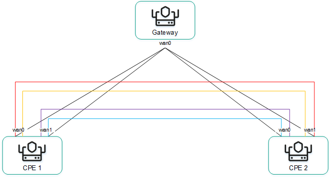
Full-Mesh topology
An example of the Partial-Mesh topology is shown in the figure below. This topology is used when direct links between some CPE devices may be undesirable, for example, for administrative reasons, or impossible for technical reasons. In this topology, the network administrator can group devices in such a way that devices in the same group communicate directly with each other, while communication with devices from other groups happens through a transit device.
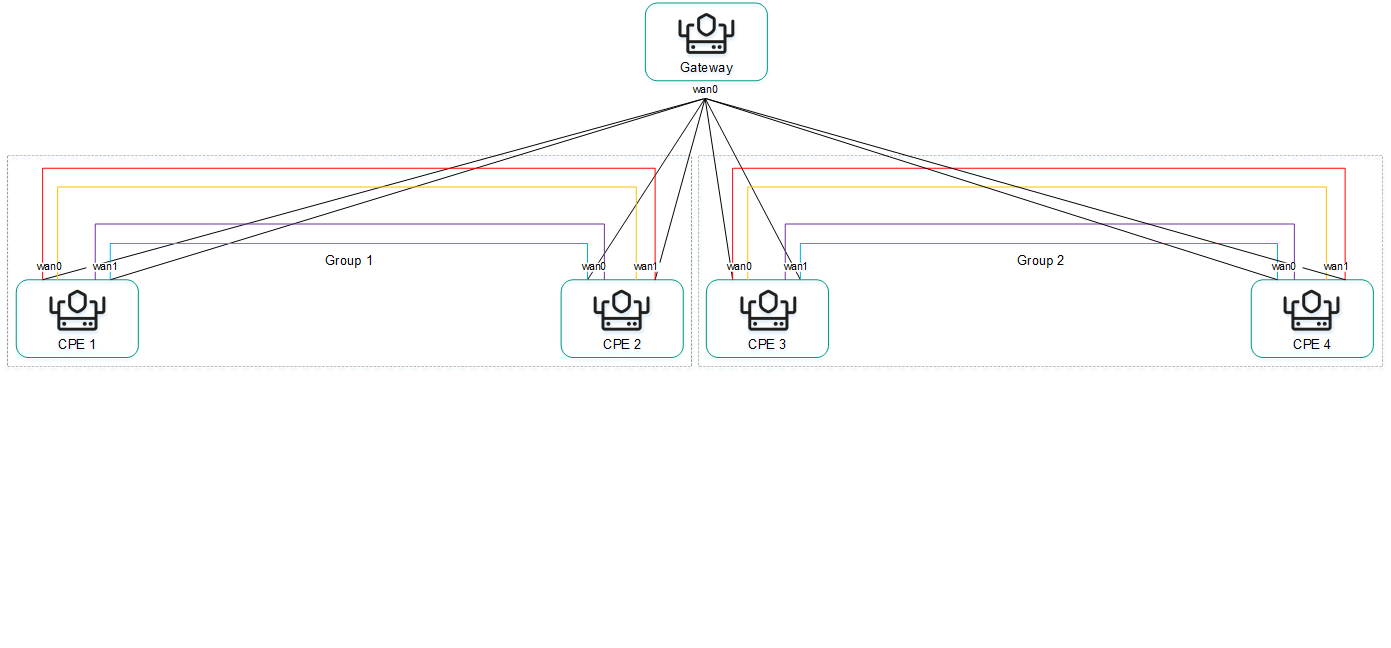
Partial-Mesh topology
A CPE device can belong to multiple groups at the same time, as shown in the figure below.
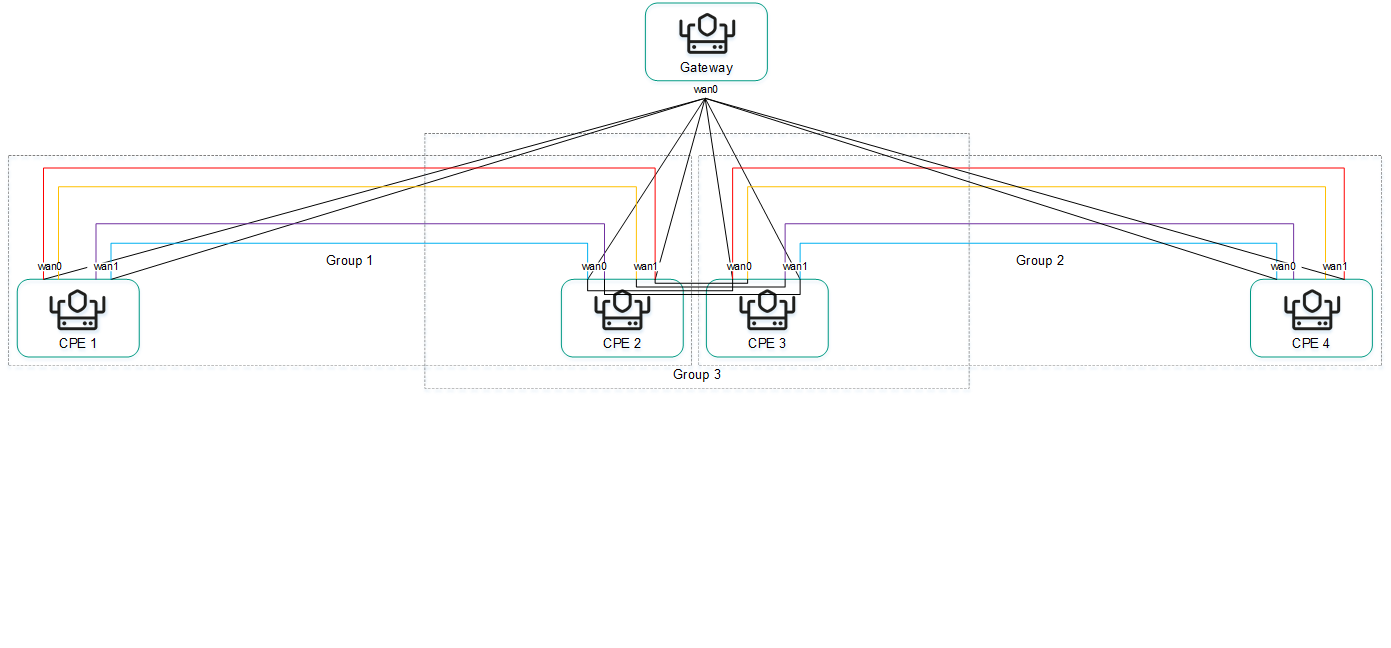
Partial-Mesh topology, CPE devices in multiple groups
When creating direct links between CPE devices, depending on the type of connectivity of the devices through physical channels, the following variants of overlay connectivity are possible:
- All physical communication channels have direct IP connectivity to each other (see the figure below). Thanks to the connectivity within the internet, CPE devices can establish the maximum number of direct links among themselves.
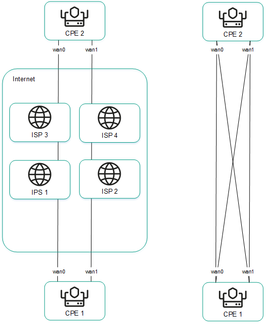
Full physical connectivity between CPE devices
- Physical communication channels have partial connectivity (see the figure below). In the example shown in the figure below, the internet cloud and the MPLS cloud are not interconnected, so links can only be established through WAN interfaces belonging to the same cloud. CPE1:WAN0 → CPE2:WAN1 and CPE1:WAN1 → CPE2:WAN0 links cannot be created.
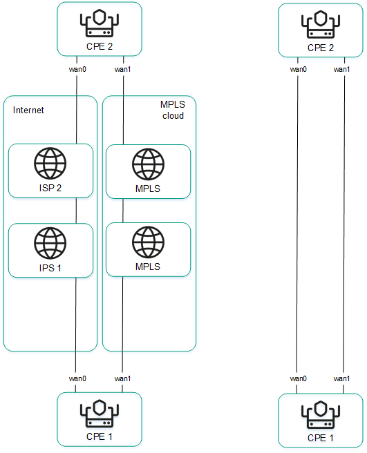
Partial physical connectivity between CPE devices
Other overlay network connectivity scenarios are also possible if IP connectivity between WAN interfaces of CPE devices within the same cloud is impossible for other reasons, for example, when using an MPLS topology that does not support direct communication between devices, or due to the presence of NAT/PAT or ACL on the internet.
Page topCreating a Hub-and-Spoke topology
A Hub-and-Spoke topology is built using roles that you assign to CPE devices. You can assign the role of a standard CPE device or an SD-WAN Gateway. Standard devices establish links with each other through SD-WAN Gateways.
By default, all devices are assigned the standard device role. To build a Hub-and-Spoke topology, at least one device must be assigned the SD-WAN Gateway role.
You can assign this role to an individual CPE device or to all devices that use the CPE template. To build a Hub-and-Spoke topology, use the following instructions:
- Assigning a role to an individual CPE device.
To assign a role to an individual CPE device:
- In the menu, go to the Infrastructure section.
The SD-WAN infrastructure management page is displayed. By default, the Network resources tab is selected, which displays the table of SD-WAN Controllers.
- Click Management next to the SD-WAN Controller and in the drop-down list, select Configuration menu.
This opens the SD-WAN Controller configuration menu. By default, you are taken to the Controller nodes section, which displays a table of Controller nodes.
- Go to the Topology tags section.
The topology tag settings are displayed.
- In the Switch drop-down list, select the CPE device.
- In the Role drop-down list, select the role for the CPE device:
- CPE for a standard CPE device.
- Gateway for an SD-WAN Gateway.
- In the upper part of the page, click Save.
You can also assign a role in the CPE device configuration.
To assign a role in the CPE device configuration:
- In the menu, go to the SD-WAN section.
By default, the CPE subsection is displayed with a table of CPE devices.
- Click the CPE device.
The settings area is displayed in the lower part of the page. You can expand the settings area to fill the entire page by clicking the expand button
 .
. - Select the Topology tab.
The topology tag settings are displayed.
- Select the Override check box to ignore the applied CPE template and make the settings in the selected tab editable. This check box is cleared by default.
- In the Switch drop-down list, select the CPE device.
- In the Role drop-down list, select the role for the CPE device:
- CPE for a standard CPE device.
- Gateway for an SD-WAN Gateway.
- In the upper part of the settings area, click Save to save the configuration of the CPE device.
- In the menu, go to the Infrastructure section.
- Assigning a role to all devices that use the CPE template.
To assign a role to all devices that use the CPE template:
- In the menu, go to the SD-WAN → CPE templates subsection.
A table of CPE templates is displayed.
- Click the CPE template.
The settings area is displayed in the lower part of the page. You can expand the settings area to fill the entire page by clicking the expand button
. - Select the Topology tab.
The topology tag settings are displayed.
- In the Role drop-down list, select a role for devices associated with the CPE template:
- CPE for a standard CPE device.
- Gateway for an SD-WAN Gateway.
- In the upper part of the settings area, click Save to save the configuration of the CPE template.
- In the menu, go to the SD-WAN → CPE templates subsection.
Creating Full-Mesh and Partial-Mesh topologies
Full-Mesh and Partial-Mesh topologies are built using topology tags that you assign to CPE devices. You can only assign topology tags to standard devices. If two devices are assigned the same topology tag, a link is automatically created between them.
In a Full-Mesh topology, all devices are assigned the same topology tag.
In a Partial-Mesh topology, devices are divided into groups based on the tags assigned to them, and communication between the devices happens through transit devices, which are devices to which tags from all groups are assigned.
You can assign a topology tag to an individual CPE device or to all devices that use the CPE template. To assign topology tags, use the following instructions:
- Assigning a topology tag to an individual CPE device.
To assign a topology tag to an individual CPE device:
- In the menu, go to the Infrastructure section.
The SD-WAN infrastructure management page is displayed. By default, the Network resources tab is selected, which displays the table of SD-WAN Controllers.
- Click Management next to the SD-WAN Controller and in the drop-down list, select Configuration menu.
This opens the SD-WAN Controller configuration menu. By default, you are taken to the Controller nodes section, which displays a table of Controller nodes.
- Go to the Topology tags section.
The topology tag settings are displayed.
- In the Switch drop-down list, select the CPE device.
- Make sure that in the Role drop-down list, the CPE option is selected. The Gateway is not used to build Full-Mesh and Partial-Mesh topologies.
- If you want to build a Partial-Mesh topology, to use a device as a transit device, select the Transit CPE check box. Transit devices are necessary to connect groups of devices together and make it possible for other devices to establish links through these transit devices.
- In the Topology tags field, enter a topology tag and click the add button
 . Devices with the same topology tags automatically establish direct links with each other.
To build a Full-Mesh topology, assign the same topology tags to all devices.
To build a Partial-Mesh topology, assign topology tags to devices based on which group they belong to. Also assign all tags used in the topology to the transit device to make sure that all device groups are added to the topology.
The topology tag is assigned and displayed below the Topology tags field.
- In the upper part of the page, click Save.
You can also assign a topology tag in the CPE device configuration.
To assign a topology tag in the CPE device configuration:
- In the menu, go to the SD-WAN section.
By default, the CPE subsection is displayed with a table of CPE devices.
- Click the CPE device.
The settings area is displayed in the lower part of the page. You can expand the settings area to fill the entire page by clicking the expand button
. - Select the Topology tab.
The topology tag settings are displayed.
- Select the Override check box to ignore the applied CPE template and make the settings in the selected tab editable. This check box is cleared by default.
- In the Switch drop-down list, select the CPE device.
- Make sure that in the Role drop-down list, the CPE option is selected. The Gateway is not used to build Full-Mesh and Partial-Mesh topologies.
- If you want to build a Partial-Mesh topology, to use a device as a transit device, select the Transit CPE check box. Transit devices are necessary to connect groups of devices together and make it possible for other devices to establish links through these transit devices.
- In the Topology tags field, enter a topology tag and click the add button . Devices with the same topology tags automatically establish direct links with each other.
To build a Full-Mesh topology, assign the same topology tags to all devices.
To build a Partial-Mesh topology, assign topology tags to devices based on which group they belong to. Also assign all tags used in the topology to the transit device to make sure that all device groups are added to the topology.
The topology tag is assigned and displayed below the Topology tags field.
- In the upper part of the settings area, click Save to save the configuration of the CPE device.
- In the menu, go to the Infrastructure section.
- Assigning a topology tag to all devices that use the CPE template.
To assign a topology tag to all devices that use the CPE template:
- In the menu, go to the SD-WAN → CPE templates subsection.
A table of CPE templates is displayed.
- Click the CPE template.
The settings area is displayed in the lower part of the page. You can expand the settings area to fill the entire page by clicking the expand button
. - Select the Topology tab.
The topology tag settings are displayed.
- Make sure that in the Role drop-down list, the CPE option is selected. The Gateway is not used to build Full-Mesh and Partial-Mesh topologies.
- If you want to build a Partial-Mesh topology, to use a device as a transit device, select the Transit CPE check box. Transit devices are necessary to connect groups of devices together and make it possible for other devices to establish links through these transit devices.
- In the Topology tags field, enter a topology tag and click the add button . Devices with the same topology tags automatically establish direct links with each other.
To build a Full-Mesh topology, assign the same topology tags to all devices.
To build a Partial-Mesh topology, assign topology tags to devices based on which group they belong to. Also assign all tags used in the topology to the transit device to make sure that all device groups are added to the topology.
The topology tag is assigned and displayed below the Topology tags field.
- In the upper part of the settings area, click Save to save the configuration of the CPE template.
- In the menu, go to the SD-WAN → CPE templates subsection.
If necessary, you can remove a topology tag from an individual CPE device or from all devices that use the CPE template. To remove topology tags, use the following instructions:
- Removing a topology tag from an individual CPE device.
To remove a topology tag from an individual CPE device:
- In the menu, go to the Infrastructure section.
The SD-WAN infrastructure management page is displayed. By default, the Network resources tab is selected, which displays the table of SD-WAN Controllers.
- Click Management next to the SD-WAN Controller and in the drop-down list, select Configuration menu.
This opens the SD-WAN Controller configuration menu. By default, you are taken to the Controller nodes section, which displays a table of Controller nodes.
- Go to the Topology tags section.
The topology tag settings are displayed.
- In the Switch drop-down list, select the CPE device.
- Click the delete button
 next to the topology tag.
The topology tag is removed and is no longer displayed.
- In the upper part of the page, click Save.
You can also remove a topology tag in the CPE device configuration.
To remove a topology tag in the CPE device configuration:
- In the menu, go to the SD-WAN section.
By default, the CPE subsection is displayed with a table of CPE devices.
- Click the CPE device.
The settings area is displayed in the lower part of the page. You can expand the settings area to fill the entire page by clicking the expand button
. - Select the Topology tab.
The topology tag settings are displayed.
- Select the Override check box to ignore the applied CPE template and make the settings in the selected tab editable. This check box is cleared by default.
- Click the delete button next to the topology tag.
The topology tag is removed and is no longer displayed.
- In the upper part of the settings area, click Save to save the configuration of the CPE device.
- In the menu, go to the Infrastructure section.
- Removing a topology tag from all devices that use the CPE template.
To remove a topology tag from all devices that use the CPE template:
- In the menu, go to the SD-WAN → CPE templates subsection.
A table of CPE templates is displayed.
- Click the CPE template.
The settings area is displayed in the lower part of the page. You can expand the settings area to fill the entire page by clicking the expand button
. - Select the Topology tab.
The topology tag settings are displayed.
- Click the delete button next to the topology tag.
The topology tag is removed and is no longer displayed.
- In the upper part of the settings area, click Save to save the configuration of the CPE template.
- In the menu, go to the SD-WAN → CPE templates subsection.