Contents
- Tunnels, segments, and paths
Tunnels, segments, and paths
Connections between CPE devices are established through tunnels that are built on top of communication channels. Tunnels are unidirectional, so when establishing a connection between two devices or between a device and the
, both an inbound link and an outbound link must be created. Tunnels established between CPE devices are combined into a topology.The concept of a tunnel is closely related to the concept of a link because in the case of SD-WAN, links are formed inside tunnels. The tunnel interface directly connects to a port of the OpenFlow switch on CPE devices on both sides, thereby forming a tunnel. Thus, in Kaspersky SD-WAN, tunnels are a means of forming links.
The set of tunnels connecting two CPEs is a segment. Traffic can be distributed over multiple tunnels at the source CPE device at the beginning of the segment and relayed to the destination CPE device at the end of the segment.
The routes along which traffic can be transmitted within one segment are called paths. The following types of paths are supported:
- Auto-SPF (Shortest-Path Forwarding) is a path that is automatically calculated by the SD-WAN Controller. Paths of this type cannot be created or deleted, and their settings cannot be edited.
- Manual-TE (Traffic Engineering) is a manually created path. To create this type of path, you need to specify the tunnels which the path traverses from the CPE device at the beginning of the segment to the device at the end of the segment.
- Auto-TE is a path automatically calculated by the SD-WAN Controller, taking into account the constraints that you specify when creating transport services. As constraints you may use the values of monitoring indicators on the tunnels, for example, the indicator of the utilization level of a tunnel.
One segment can contain from 2 to 16 paths, and when transmitting traffic, the best path with the lowest value of the cost parameter is selected by default. If the best path is not available for traffic transmission for technical reasons, another path with the closest value of the cost parameter is selected.
Configuring paths
You can specify path settings on an individual CPE device, on all devices that use the CPE template, or on all devices in a segment. Use the following instructions to configure paths:
- Configuring paths on an individual CPE device.
To configure paths on an individual CPE device:
- In the menu, go to the SD-WAN section.
By default, the CPE subsection is displayed with a table of CPE devices.
- Click the CPE device.
The settings area is displayed in the lower part of the page. You can expand the settings area to fill the entire page by clicking the expand button
 .
. - Select the Multipathing tab.
Path settings are displayed.
- In the Maximum number of paths field, enter the maximum number of paths supported by the CPE device or segment. Range of values: 1 to 16. The default setting is
8. - In the Maximum of Auto-SPF field, enter the maximum number of Auto-SPF paths supported by the CPE device or segment. Paths of the Auto SPF type are automatically calculated by the SD-WAN Controller. Range of values: 1 to 8. The default setting is
2. - In the Cost variance multiplier field, enter the cost variance factor that determines how many times greater the cost of a route can be compared to the best route, to make the path eligible for being added to the segment. Range of values: 1.0 to 10.0.
The default setting is
10. You cannot enter a value in this field if the Multi-weight balancing check box is selected. - If you need to distribute traffic among paths approximately in proportion to the value of the Path.weight attribute, select the Multi-weight balancing check box. When the check box is cleared, traffic is evenly spread and the weight attribute for all paths is 1. This check box is selected by default.
- Click Apply.
- In the menu, go to the SD-WAN section.
- Configuring paths on all devices that use a CPE template.
To configure paths on all devices that use a CPE template:
- In the menu, go to the SD-WAN → CPE templates subsection.
A table of CPE templates is displayed.
- Click the CPE template.
The settings area is displayed in the lower part of the page. You can expand the settings area to fill the entire page by clicking the expand button
. - Select the Multipathing tab.
Path settings are displayed.
- In the Maximum number of paths field, enter the maximum number of paths supported by the CPE device or segment. Range of values: 1 to 16. The default setting is
8. - In the Maximum of Auto-SPF field, enter the maximum number of Auto-SPF paths supported by the CPE device or segment. Paths of the Auto SPF type are automatically calculated by the SD-WAN Controller. Range of values: 1 to 8. The default setting is
2. - In the Cost variance multiplier field, enter the cost variance factor that determines how many times greater the cost of a route can be compared to the best route, to make the path eligible for being added to the segment. Range of values: 1.0 to 10.0.
The default setting is
10. You cannot enter a value in this field if the Multi-weight balancing check box is selected. - If you need to distribute traffic among paths approximately in proportion to the value of the Path.weight attribute, select the Multi-weight balancing check box. When the check box is cleared, traffic is evenly spread and the weight attribute for all paths is 1. This check box is selected by default.
- In the upper part of the settings area, click Save to save the configuration of the CPE template.
- In the menu, go to the SD-WAN → CPE templates subsection.
- Configuring paths on all devices in a segment.
Creating a Manual-TE path
To create a Manual-TE path, you must specify the links which the path traverses from the CPE device at the start of the segment to the CPE device at the end of the segment. Two types of such paths are supported:
- Fully defined paths that identify each device and interface from the beginning to the end of the segment. In this case, you must specify each link traversed by the path.
- Hybrid paths in which you can specify one or more intermediate devices and, if necessary, interfaces. In this case, traffic is automatically transmitted between network nodes that are not manually specified (the Auto-SPF path is used).
You can use constraints to add Manual-TE paths to transport services.
Examples of possible Manual-TE paths: In the above examples, the abbreviation Sw (switch) stands for CPE devices. The interface number is indicated after the device number, separated by a colon. Fully defined path: Sw1:3 → Sw2:1, Sw2:2 → Sw4:1, Sw4:5 → SwN:2. Hybrid path: Sw1 → Sw5, Sw5:3 → Sw4:3, Sw4 → SwN. In this case, the path from Sw1 to SwN is constructed as the Auto-SPF path between Sw1 and Sw5, the Sw5:3 → Sw4:3 link, and the Auto-SPF path between Sw4 and SwN. |
To create a Manual-TE path:
- In the menu, go to the Infrastructure section.
The SD-WAN infrastructure management page is displayed. By default, the Network resources tab is selected, which displays the table of SD-WAN Controllers.
- Click Management next to the SD-WAN Controller and in the drop-down list, select Configuration menu.
This opens the SD-WAN Controller configuration menu. By default, you are taken to the Controller nodes section, which displays a table of Controller nodes.
- Go to the Segments section.
A table of segments is displayed.
- Click Management next to the segment and in the drop-down list, select Edit.
This opens a window with path settings and a table of paths.
- Click + Manual-TE path.
This opens a window with the Manual-TE path settings and a table of hops.
- In the Name field, enter the name of the Manual-TE path.
- In the Maximum number of hops field, enter the maximum number of hops in the path. Range of values: 1 to 8. The default setting is
4. - In the From drop-down list on the left, select the starting CPE device for the hop.
If no hops are created in the path, only the first device of the segment can be selected as the starting CPE device.
If at least one hop is created in the path, only the final device of the last hop can be selected as the starting CPE device.
- If necessary, in the Port drop-down list on the left, select the network-to-network interface (NNI) of the starting CPE device for the hop. The default setting is AUTO and the interface is detected automatically.
- In the To drop-down list on the right, select the CPE device at the end of the hop.
When the starting CPE device of a hop is set to AUTO in the Port drop-down list, you can select any device in the domain as the final device except those that are already being used in other hops. For the final hop, the AUTO value is automatically selected in the Port drop-down list. Thus, the hop uses an Auto-SPF path.
If an NNI is selected for the starting CPE device for a hop in the Port drop-down list, only the device to which a link has been constructed from the NNI can be selected as the final device. For the final device of the hop, the NNI to which the path is constructed is automatically selected in the Port drop-down list. Thus, the hop uses the link specified between the two devices.
- If necessary, in the Port drop-down list on the right, select the network-to-network interface (NNI) of the CPE device at the end of the hop. The default setting is AUTO and the interface is detected automatically.
- Click Add to add a hop to the Manual-TE path.
The hop is created and displayed in the table. The Segments column displays the cost of the hop, which is the sum of the cost of all links added to it. You can add multiple hops if the maximum number of hops in the path is not reached.
- Click Create.
A check is performed to see that the final device of the last hop matches the final device of the segment in which you are creating the Manual-TE path. If the check is successful, the Manual-TE path is created and added to the table, and the Cost column displays the cost of the path, which is the sum of the cost of all hops added to it.
Page topEditing a Manual-TE path
To edit a Manual-TE path:
- In the menu, go to the Infrastructure section.
The SD-WAN infrastructure management page is displayed. By default, the Network resources tab is selected, which displays the table of SD-WAN Controllers.
- Click Management next to the SD-WAN Controller and in the drop-down list, select Configuration menu.
This opens the SD-WAN Controller configuration menu. By default, you are taken to the Controller nodes section, which displays a table of Controller nodes.
- Go to the Segments section.
A table of segments is displayed.
- Click Management next to the segment and in the drop-down list, select Edit.
This opens a window with path settings and a table of paths.
- Click Edit next to the Manual-TE path.
This opens a window with the Manual-TE path settings and a table of hops.
- Edit the settings as necessary. For a description of the settings, see the instructions for creating a Manual-TE path.
- Click Save to save the settings of the Manual-TE path.
- Click Save to save the settings of the segment.
Deleting a hop from a Manual-TE path
Hops deleted from a Manual-TE path cannot be restored.
To delete a hop from the Manual-TE transport path:
- In the menu, go to the Infrastructure section.
The SD-WAN infrastructure management page is displayed. By default, the Network resources tab is selected, which displays the table of SD-WAN Controllers.
- Click Management next to the SD-WAN Controller and in the drop-down list, select Configuration menu.
This opens the SD-WAN Controller configuration menu. By default, you are taken to the Controller nodes section, which displays a table of Controller nodes.
- Go to the Segments section.
A table of segments is displayed.
- Click Management next to the segment and in the drop-down list, select Edit.
This opens a window with path settings and a table of paths.
- Click Edit next to the Manual-TE path.
This opens a window with the Manual-TE path settings and a table of hops.
- Click Delete next to the hop.
The hop is deleted and is no longer displayed in the table.
- Click Save to save the settings of the Manual-TE path.
- Click Save to save the settings of the segment.
Deleting a Manual-TE path
Deleted Manual-TE paths cannot be restored.
To delete a Manual-TE path:
- In the menu, go to the Infrastructure section.
The SD-WAN infrastructure management page is displayed. By default, the Network resources tab is selected, which displays the table of SD-WAN Controllers.
- Click Management next to the SD-WAN Controller and in the drop-down list, select Configuration menu.
This opens the SD-WAN Controller configuration menu. By default, you are taken to the Controller nodes section, which displays a table of Controller nodes.
- Go to the Segments section.
A table of segments is displayed.
- Click Management next to the segment and in the drop-down list, select Edit.
This opens a window with path settings and a table of paths.
- Click Delete next to the Manual-TE path.
The Manual-TE path is deleted and is no longer displayed in the table.
- Click Save to save the settings of the segment.
Specifying the cost of a link
You can specify the cost of an individual link. All links built within the SD-WAN network are displayed in the overall table of links in the Tunnels section, as well as in the graphic topology in the Topology section. A table of links built using a particular CPE device is also displayed in the configuration of that CPE device, on the Tunnels tab.
To indicate the cost of the link, use the following instructions:
- Specify the cost of the link using the overall link table.
- Specify the cost of a link using the graphical topology.
- Specifying the cost of a link in the configuration of the CPE device.
To specify the cost of a link on an individual CPE device:
- In the menu, go to the SD-WAN section.
By default, the CPE subsection is displayed with a table of CPE devices.
- Click the CPE device.
The settings area is displayed in the lower part of the page. You can expand the settings area to fill the entire page by clicking the expand button
. - Select the Tunnels tab.
A table of links is displayed.
- Click Management next to the link and in the drop-down list, select Set cost.
- This opens a window; in that window, select the Override check box to specify the cost of the link.
- In the Tunnel cost field, enter the cost of the link.
- To automatically assign the specified cost to the corresponding link in the opposite direction, select the Save for both tunnels check box.
- Click Save.
- In the upper part of the settings area, click Save to save the configuration of the CPE device.
- In the menu, go to the SD-WAN section.
Enabling Dampening
Dampening is a configurable mechanism that prevents the use of links that change state too frequently. When determining instability, the following state changes are taken into account:
- UP/LIVE → DOWN/NOT-LIVE.
- DOWN/NOT-LIVE → UP/LIVE.
- UP/LIVE → UP/NOT-LIVE.
- UP/NOT-LIVE → UP/LIVE.
The LIVE and NOT-LIVE states are used to integrate the Dampening function with the Ethernet Connectivity Fault Management (CFM) protocol, which detects the loss of two-way Ethernet connectivity of the segment between neighbor switches without the service interface entering the DOWN state (Rx signal loss).
Dampening is applied to both ends of the Ethernet segment.
This functionality does the following within a deployed SD-WAN network:
- Detect frequent changes of the states of service interfaces.
- Move transport services suffering from instability of service interfaces to backup links.
- Exclude segments tied to the service interfaces from route calculation for transport services.
When the Dampening functionality is enabled, each state change of the service interface through which the link is constructed increases the Penalty value. If the Penalty factor reaches the threshold value within a certain period of time, access to the link is restricted (its cost is increased 10,000 times for a certain period of time). The value of each of these parameters is specified when you enable the feature. By default, access to the link is resumed if the state of the service interface does not change for 10 minutes.
You can enable Dampening on an individual link. All links built within the SD-WAN network are displayed in the overall table of links in the Tunnels section, as well as in the graphic topology in the Topology section. A table of links built using a particular CPE device is also displayed in the configuration of that CPE device, on the Tunnels tab.
To enable Dampening on a link, use the following instructions:
- Enabling Dampening on a link using the overall table of links.
- Enabling Dampening on a link using the graphical topology.
- Enabling Dampening on a link in the configuration of an individual CPE device.
To enable Dampening on a link on an individual CPE device:
- In the menu, go to the SD-WAN section.
By default, the CPE subsection is displayed with a table of CPE devices.
- Click the CPE device.
The settings area is displayed in the lower part of the page. You can expand the settings area to fill the entire page by clicking the expand button
. - Select the Tunnels tab.
A table of links is displayed.
- Click Management next to the link and in the drop-down list, select Dampening.
- This opens a window, in that window, select the Enable check box.
- In the Maximum suppress time (ms.) field, enter the maximum length of time, in milliseconds, for which access to the link can be restricted. When the specified time elapses, all Dampening counters on the link are reset. The default setting is
600,000. - In the Penalty, enter the number by which Penalty is incremented when the link changes state. The default setting is
1. - In the Suppress threshold field, enter the Penalty value at which access to the link is restricted. The default setting is
4. - In the Update interval (ms.) field, enter the time in milliseconds during which Penalty must attain the value specified in the Suppress threshold field for access to the link to be restricted. The default setting is
120,000. - To view Dampening statistics for a link, click Load statistics.
- Click Save.
- In the upper part of the settings area, click Save to save the configuration of the CPE device.
- In the menu, go to the SD-WAN section.
Enabling Forward Error Correction
The Forward Error Correction (FEC) functionality reduces the loss of traffic packets in communication channels, especially for UDP applications, and the number of retransmissions, which lead to delays, and also recovers received data on the CPE device. Data recovery is provided by redundant encoding of the data stream on the device on the sending side.
We recommend using FEC on noisy links to reduce the packet loss and increase the speed of TCP connections.
The sender CPE encodes the stream of traffic packets egressing into the tunnel, adding redundant packets. The use of encoding on the sending and receiving sides may cause delays due to extra data processing. You can configure the degree of redundancy in the settings of the SD-WAN Controller or when you enable FEC.
The receiving CPE device buffers traffic packets received through the tunnel and decodes them, recovering lost packets, if possible. The general diagram of FEC is shown in the figure below.
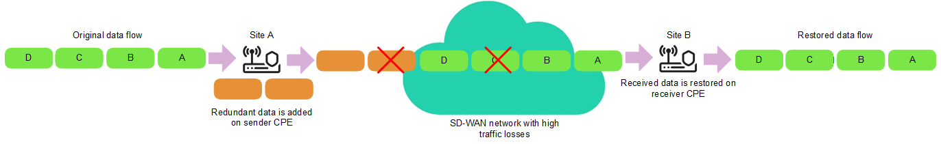
FEC diagram
You can enable FEC on an individual tunnel. All links built within the SD-WAN network are displayed in the overall table of links in the Tunnels section, as well as in the graphic topology in the Topology section. A table of links built using a particular CPE device is also displayed in the configuration of that CPE device, on the Tunnels tab.
To enable FEC on a tunnel, use the following instructions:
- Enabling FEC on a tunnel using the overall table of tunnels.
- Enabling FEC on a tunnel using the graphical topology.
- Enabling FEC on a link in the configuration of an individual CPE device.
To enable FEC on a link in the configuration of an individual CPE device:
- In the menu, go to the SD-WAN section.
By default, the CPE subsection is displayed with a table of CPE devices.
- Click the CPE device.
The settings area is displayed in the lower part of the page. You can expand the settings area to fill the entire page by clicking the expand button
. - Select the Tunnels tab.
A table of tunnels is displayed.
- Click Management next to the tunnel and in the drop-down list, select FEC/reordering.
- This opens a window; in that window, select the Override check box to configure FEC on the tunnel.
- In the Redundancy ratio (original/redundant packet) drop-down list, select the degree of redundancy of transmitted traffic packets, which is the ratio between the original packets and extra packets containing redundant code. The default setting is 0:0 FEC off and the functionality is not active.
- In the Timeout field, enter the maximum time, in milliseconds, during which a traffic packet can stay in the queue for FEC to apply. Range of values: 1 to 1000.
- Click Save.
- In the upper part of the settings area, click Save to save the configuration of the CPE device.
- In the menu, go to the SD-WAN section.
Determining the effective MTU in a link
Kaspersky SD-WAN can determine the supported MTU (maximum transmission unit) size on links between two devices (a CPE device and an SD-WAN gateway or between two CPE devices).
Determining the maximum MTU size on links is necessary to ensure the passage of user traffic through the SD-WAN network when the MTU on the underlay network is too low, and fragmented packets are blocked on the subsequent hop (see the figure below).
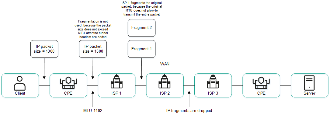
Example of a link with a reduced MTU size and fragmented packet getting dropped
The supported MTU size is calculated by sending variable-payload LLDP packets through all links on the CPE device and the SD-WAN gateway. The minimum detectable MTU size is 1,280 bytes, and the maximum size is 1,500 bytes.
The supported MTU size is calculated:
- When the CPE device is turned on.
- With the frequency set in the topology.link.pmtud.scheduler.interval.sec
propertyof the SD-WAN Controller. By default, the frequency is set to 86,400 seconds. - Manually when you request it.
You can calculate the supported MTU size on an individual link. All links built within the SD-WAN network are displayed in the overall table of links in the Tunnels section, as well as in the graphic topology in the Topology section. A table of links built using a particular CPE device is also displayed in the configuration of that CPE device, on the Tunnels tab.
Supported MTU sizes are displayed in the MTU column of the link table. If the value has not been calculated yet, the Unknown value is displayed.
To calculate the MTU on a link, use the following instructions:
- Calculating the MTU on a link using the overall table of links.
- Calculating the MTU on a link in the configuration of a CPE device.
To calculate the MTU on a link in the configuration of a CPE device:
- In the menu, go to the SD-WAN section.
By default, the CPE subsection is displayed with a table of CPE devices.
- Click the CPE device.
The settings area is displayed in the lower part of the page. You can expand the settings area to fill the entire page by clicking the expand button
. - Select the Tunnels tab.
A table of links is displayed.
- Click Management next to the link and in the drop-down list, select Check MTU.
The test result is displayed in the MTU column.
- In the menu, go to the SD-WAN section.
Package fragmentation
Fragmentation is the process of dividing traffic packets transmitted over the network into parts (fragments), each of which does not exceed the MTU size of the route. Kaspersky SD-WAN checks whether fragmentation of traffic packets is supported on each CPE device.
The MTU size determines the maximum amount of data that can be transmitted over the network in a single traffic packet. Fragmentation problems within the SD-WAN network can cause data transfer to become unstable or to stop completely.
A packet fragmentation test is started automatically. When enabled, each CPE device sends two ICMP requests from all WAN ports to IP addresses that you specified when creating SD-WAN interfaces or in the SD-WAN Controller configuration file when deploying the solution.
The ICMP requests have a packet size of 1,600 bytes. If at least one of these requests receives a response, a conclusion is made that the CPE device supports packet fragmentation.
A packet fragmentation test on a CPE device may yield one of the following results:
- Unsupported means the device cannot transmit fragmented packets.
- Unknown means the software installed on the CPE device does not support testing packet fragmentation.
- Supported means the device can transmit fragmented packets.
The fragmentation test result is displayed in the Fragmentation column of the overall table of links in the Tunnels section, as well as in the column of the same name in the link table in the configuration on the CPE device, on the Tunnels tab. Only links built using the particular CPE device are displayed in the configuration of that device.
Page topTraffic encryption
Traffic encryption is a mechanism of securing the exchange of traffic between
through tunnels. For example, you can encrypt traffic when sending data between devices over a tunnel built on top of an unsecured Internet connection.Traffic encryption does not replace the need to use other information security measures, such as TLS, LDAPS, and other protocols that protect traffic within the overlay network.
The
automatically generates keys for encrypting and decrypting traffic and sends them to CPE devices. Traffic is encrypted on the source device with an encryption key before being sent to the tunnel. The destination device receives traffic from the tunnel and decrypts it with the decryption key.The keys are regularly updated to deprive third parties of the opportunity to encrypt or decrypt the transmitted traffic if a key is intercepted. You can specify the length of time after which the keys are updated on CPE devices using the Dtopology.link.encryption.key.update.interval.minutes property of the SD-WAN Controller.
Traffic encryption is supported only on CPE devices running Kaspersky SD-WAN software.
If traffic encryption is enabled on a CPE device, all outbound tunnels that involve this device send encrypted traffic (including new tunnels that will be established later).
If traffic encryption is disabled on a CPE device, it sends unencrypted traffic. Note that if you disable traffic encryption on a device that previously encrypted its outgoing traffic, the keys generated by the SD-WAN Controller for encrypting and decrypting traffic are deleted from all associated devices.
Traffic encryption can also be enabled or disabled on tunnels. For example, you can enable traffic encryption on a CPE device, but disable it on a tunnel established with the participation of this device. When enabling or disabling traffic encryption on a tunnel, you must configure both the outgoing and incoming tunnels in the same way.
Traffic encryption on a CPE device
If traffic encryption is enabled on a CPE device, encrypted traffic is transmitted through all links established with its participation. The exception is cases when you enable traffic encryption on the device, but disable it on an individual link.
You can enable or disable traffic encryption on an individual CPE device or on all devices that use the CPE template. By default, traffic encryption is disabled.
To enable or disable traffic encryption on an individual CPE device:
- In the menu, go to the SD-WAN section.
By default, the CPE subsection is displayed with a table of CPE devices.
- Click the CPE device.
The settings area is displayed in the lower part of the page. You can expand the settings area to fill the entire page by clicking the expand button
. - Select the Tunnel encryption tab.
The traffic encryption policy is displayed.
- Select the Override check box to ignore the applied CPE template and make the settings in the selected tab editable. This check box is cleared by default.
- In the Default encryption policy drop-down list, select Enabled or Disabled.
- In the upper part of the settings area, click Save to save the configuration of the CPE device.
To enable or disable traffic encryption on all devices that use a CPE template:
- In the menu, go to the SD-WAN → CPE templates subsection.
A table of CPE templates is displayed.
- Click the CPE template.
The settings area is displayed in the lower part of the page. You can expand the settings area to fill the entire page by clicking the expand button
. - Select the Tunnel encryption tab.
The traffic encryption policy is displayed.
- In the Default encryption policy drop-down list, select Enabled or Disabled.
- In the upper part of the settings area, click Save to save the configuration of the CPE template.
Traffic encryption on a link
You can enable or disable traffic encryption on an individual link. All links built within the SD-WAN network are displayed in the overall table of links in the Tunnels section, as well as in the graphic topology in the Topology section. A table of links built using a particular CPE device is also displayed in the configuration of that CPE device, on the Tunnels tab.
When enabling or disabling traffic encryption on an individual link, you must configure the opposite-direction link in the same way.
To enable or disable traffic encryption on a link, use the following instructions:
- Enabling or disabling traffic encryption on a link using the overall table of links.
- Enabling or disabling traffic encryption on a link using the graphical topology.
- Enabling or disabling traffic encryption on a link in the configuration of a CPE device.
To enable or disable traffic encryption on a link in the configuration of a CPE device:
- In the menu, go to the SD-WAN section.
By default, the CPE subsection is displayed with a table of CPE devices.
- Click the CPE device.
The settings area is displayed in the lower part of the page. You can expand the settings area to fill the entire page by clicking the expand button
. - Select the Tunnels tab.
A table of links is displayed.
- Click Management next to the link and in the drop-down list, select Set encryption.
- This opens a window; in that window, select or clear the Override check box to enable or disable encryption of the selected link. This check box is cleared by default.
- Select or clear the Enable encryption check box. This check box is cleared by default.
- In the upper part of the settings area, click Save to save the configuration of the CPE device.
- In the menu, go to the SD-WAN section.