Contents
- Managing network services
- User roles and actions with network services
- Uploading a VNF or PNF package to the orchestrator
- Network service template
- Creating a network service
- Configuring network service topology components
- Editing a network service topology
- Deploying a network service
- Checking the consistency of a network service
- Redeploying a network service and its components
- Auto-Healing
- Managing VNFs and VDUs in a network service
- Viewing the network service log
- Deleting a network service
Managing network services
Network services relay traffic over the network and apply network functions such as WAN optimization, traffic shaping and identification, and data protection. Multiple network services can be combined into a service chain to sequentially apply the functions of these services to traffic when it is transmitted to its destination.
You can create a network service template to easily deploy this service within tenants.
The main network service responsible for the deployment and operation of Kaspersky SD-WAN is the SD-WAN service. This service is the first to be created, it encompasses the components that are part of the
. At least one SD-WAN service is deployed within each SD-WAN instance.Network services and their templates are created using a graphical design tool. It allows visually constructing a service topology by placing the following components into it:
- Network components such as VNF and PNF.
- Links, such as P2P, P2M and M2M transport services, as well as OpenStack connections, such as the OS 2 Shared network.
- UNIs and WAN interfaces.
Links are connected to network components and interfaces to create the topology of the network service. You can link separately created network services by placing a shared network service (shared NS) in their topology.
An example of a network service topology is shown in the figure below.
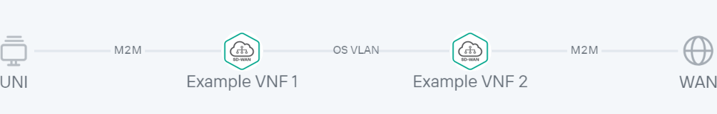
An example of a network service topology
User roles and actions with network services
The table below lists user roles and the actions they can perform to manage network services. If you have the platform administrator role, you can authenticate in the web interface of the tenant as an administrator and perform the needed actions.
User roles and actions with network services that are available to them
Action |
Platform administrator |
Tenant administrator |
|---|---|---|
Creating network service templates |
|
|
Uploading a VNF or PNF package to the catalog |
|
|
Configuring network components |
|
|
Creating and deploying network services |
|
|
Viewing deployed network services |
|
|

Uploading a VNF or PNF package to the orchestrator
VNF and PNF packages are ZIP archives that contain the components necessary for deploying and managing virtual and physical network functions. You can prepare your own network function package and define how the management interface of function must appear in the web interface of the orchestrator.
Each package has the following structure:
- VNFD (Virtual Network Function descriptor) or PNFD (Physical Network Function descriptor) descriptor files in YAML format. These are configuration files that provide detailed information about the network function, and contain specifications such as specifications for deployment, network connections, and hardware resources.
- The 'scripts' folder. This folder contains scripts and executable files that are used to deploy and configure the network function. For example, scripts may include automation tasks, installation operations, and unique actions that are required for deployment.
The VNF package structure additionally includes the 'images' folder, which contains image files as well as resources necessary for the proper functioning of the VNF, such as binaries, firmware, and icons.
If you have the platform administrator role, you must upload the VNF and/or PNF package to the orchestrator web interface to gain the ability to add them to the network service topology and apply them to traffic passing through these services.
Note that the SD-WAN Controller is also deployed as a VNF or PNF.
To upload a VNF or PNF package to the orchestrator:
- In the menu, go to the Catalog section.
The network service management page is displayed.
- In the upper part of the page, click + VNF or + PNF.
- Select a VNF or PNF package file.
The uploaded network function is displayed in the Catalog panel.
Page topNetwork service template
You can create a network service template and assign it to the tenants for which you want to deploy that network service. This lets you avoid the need to create a network service for each of your tenants individually.
When creating a template, a network service topology is constructed, with all the necessary network components, connections, and interfaces that connect to each other. A tenant to which a template is assigned can replace abstract topology components with real ones and deploy the network service.
Creating a network service template
Before creating a template, you must upload all necessary VNF or PNF packages to the orchestrator.
To create a network service template:
- In the menu, go to the Catalog section.
The network service management page is displayed.
- In the upper part of the page, click + Template.
The graphical design tool for building the network service topology is displayed.
- Drag the following network components from the Catalog pane to the graphical design tool to add them to the topology:
- .
- .
- Shared network services. If a shared network service is added to a topology of multiple network services, it can be used to interconnect those network services.
- Network service template. If, when creating a network service template, you place another template in the topology, the topology is constructed in accordance with that template, and you can then edit the topology by adding or removing components.
To remove an added network component, click it and select Delete from the drop-down list.
- Drag the following links from the Links tab in the lower part of the screen to the graphical design tool to add the links to the topology:
- P2P — P2P transport service
- P2M — P2M transport service
- M2M — M2M transport service
The remaining links are relevant to network communication at the VIM level and are established between VNFs hosted by the OpenStack cloud platform:
- OS shared — a network that can be shared by multiple tenants
- OS vRouter — a router that provides L3 routing
- OS VLAN — a network for transmitting tagged L2 traffic of the 802.1Q standard
- OS VXLAN — a network that provides VXLAN tunneling
- OS flat — a network for transmitting untagged L2 traffic
To remove an added link click it and select Delete from the drop-down list.
- In the lower part of the page, select the UNI tab and drag UNI and/or WAN interfaces to the graphical design tool to add them to the topology. To remove an added interface, click it and select Delete from the drop-down list.
- Configure topology components.
- Connect the links to the network components:
- Click a link and in the drop-down list, select Add leaf to connect a network component that has the Leaf role. If you clicked a P2M service, you can select Add root in the drop-down list to connect a network component that has the Root role.
- Click the network component icon and in the displayed window, select an interface for the connection.
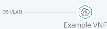
The link is connected to the network component, which is indicated in the topology by a line between them. For example, the figure below shows a VLAN connected to a VNF.
- Connect the links to interfaces:
- Click a link and in the drop-down list, select Add leaf to connect an interface that has the Leaf role. If you clicked a P2M service, you can select Add root in the drop-down list to connect an interface that has the Root role.
- Click the intefrace icon.
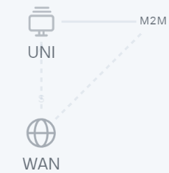
The link is connected to the interface, which is indicated in the topology by a line between them. For example, the figure below shows a P2P service connected to a UNI and WAN interface.

- If necessary, assign backup interfaces to the UNI:
- Click the UNI and in the drop-down list, select Reserve.
A backup interface can be assigned only for UNIs to which at least one link is connected.
- Click the icon of the interface that you want to use as a reserve interface.
The interface is designated as the backup interface for the UNI, and a dotted line is displayed between the UNI, the backup interface, and the link connected to the UNI. For example, in the figure below, the WAN interface is the backup interface for the UNI.
- Click the UNI and in the drop-down list, select Reserve.
- If necessary, do the following:
- Select the Description check box to display a description under each topology component. This check box is selected by default.
- ClickArrange to align topology components vertically.
- In the Name field, enter the name of the network service.
- In the upper part of the page, click Save.
The network service template is created and displayed in the Catalog panel, on the Templates tab.
Page topDeleting a network service template
Deleted network service templates cannot be restored.
To delete a network service template:
- In the menu, go to the Catalog section.
The network service management page is displayed.
- In the Catalog pane, select the Templates tab.
A list of network service templates is displayed.
- Click the delete button
 next to the network service template.
 - In the confirmation window, click Delete.
The network service template is deleted and is no longer displayed in the Catalog panel.
Page topCreating a network service
You can create a network service manually or using a template. When you use a template to create a network service, the topology of the service is built in accordance of the topology of the template, and you can then modify it by adding or removing components.
To create a network service:
- In the menu, go to the Catalog section.
The network service management page is displayed.
- In the Network services panel, click + Network service.
The graphical design tool for building the network service topology is displayed.
- If you want to use a template to create the network service, drag the template from the Catalog pane to the graphic designer.
The topology is constructed in accordance with that template.
- Drag the following network components from the Catalog pane to the graphical design tool to add them to the topology:
- Virtual network functions.
- Physical network functions.
- Shared network services. If a shared network service is added to a topology of multiple network services, it can be used to interconnect those network services.
When adding a network function, in the window that is displayed, select where you want to place it — in the data center or on the uCPE device.
To remove an added network component, click it and select Delete from the drop-down list.
- Drag the following links from the Links tab in the lower part of the screen to the graphical design tool to add the links to the topology:
- P2P — P2P transport service
- P2M — P2M transport service
- M2M — M2M transport service
The remaining links are relevant to network communication at the VIM level and are established between VNFs hosted by the OpenStack cloud platform:
- OS shared — a network that can be shared by multiple tenants
- OS vRouter — a router that provides L3 routing
- OS VLAN — a network for transmitting tagged L2 traffic of the 802.1Q standard
- OS VXLAN — a network that provides VXLAN tunneling
- OS flat — a network for transmitting untagged L2 traffic
When adding a OS VLAN, OS VXLAN, or OS flat connection, in the window that is displayed, select where you want to place it — in the data center or on the uCPE device.
To remove an added link click it and select Delete from the drop-down list.
- In the lower part of the page, select the UNI tab and drag UNI and/or WAN interfaces to the graphical design tool to add them to the topology. To remove an added interface, click it and select Delete from the drop-down list.
- Configure topology components.
- Connect the links to the network components:
- Click a link and in the drop-down list, select Add leaf to connect a network component that has the Leaf role. If you clicked a P2M service, you can select Add root in the drop-down list to connect a network component that has the Root role.
- Click the network component icon and in the displayed window, select an interface for the connection.
The link is connected to the network component, which is indicated in the topology by a line between them. For example, the figure below shows a VLAN connected to a VNF.
- Connect the links to interfaces:
- Click a link and in the drop-down list, select Add leaf to connect an interface that has the Leaf role. If you clicked a P2M service, you can select Add root in the drop-down list to connect an interface that has the Root role.
- Click the intefrace icon.
The link is connected to the interface, which is indicated in the topology by a line between them. For example, the figure below shows a P2P service connected to a UNI and WAN interface.
- If necessary, assign backup interfaces to the UNI:
- Click the UNI and in the drop-down list, select Reserve.
A backup interface can be assigned only for UNIs to which at least one link is connected.
- Click the icon of the interface that you want to use as a reserve interface.
The interface is designated as the backup interface for the UNI, and a dotted line is displayed between the UNI, the backup interface, and the link connected to the UNI. For example, in the figure below, the WAN interface is the backup interface for the UNI.
- Click the UNI and in the drop-down list, select Reserve.
- If necessary, do the following:
- Select the Description check box to display a description under each topology component. This check box is selected by default.
- ClickArrange to align topology components vertically.
- In the Name field, enter the name of the network service.
- Complete the network service creation:
- To save the network service, click Save.
- To save and immediately deploy a network service, click Deploy.
The network service is created and displayed in Network services panel. If you clicked Deploy, the deployment of the network service begins, which may take several minutes. You can interrupt the deployment by clicking Abort deploy.
Page topConfiguring network service topology components
You can configure network components, connections, and interfaces added to the topology of a network service template or an individual network service. Before you can configure topology components, you must open the topology.
To open the topology:
- In the menu, go to the Catalog section.
The network service management page is displayed.
- Open the topology:
- If you want to open the topology of a network service template, select the template in the Catalog panel.
- If you want to open the topology of a network service, select the network service in the Network services panel.
The graphical design tool with the network service topology is displayed.
Use the following instructions to configure topology components:
- Configuring a VNF in the network service topology
To configure a VNF in the topology:
- Click the VNF.
The settings area is displayed in the lower part of the page. You can expand the settings area to fill the entire page by clicking the expand button
 .
.By default, the Flavours tab is selected, which displays the flavours of virtual machines for the network function. Flavours are described in the VNF package.
- Select the Connection points tab and configure the VNF interfaces:
- In the Type drop-down list, select how you want to assign an IP address and subnet mask to the interface:
- DHCP reservation to assign an IP address and subnet mask using DHCP.
- AUTO to automatically assign an IP address and subnet mask. This is the default setting.
- If in the Type drop-down list, you selected DHCP reservation, follow these steps:
- In the IP field, enter the IP address of the interface.
- In the Mask field, enter the subnet mask.
- In the Description field, enter a brief description of the interface.
- If you want to make the interface a trunk port for processing traffic from multiple VLANs simultaneously, select the Trunk check box. When the check box is selected, the VNF interface is capable of transmitting and receiving tagged VLAN traffic, which contains an additional identifier (VLAN tag) that lets you identify and filter different VLANs in the network. This check box is cleared by default.
- In the Type drop-down list, select how you want to assign an IP address and subnet mask to the interface:
- Select the VNF settings tab and specify general VNF settings:
- In the Name field, enter the name of the VNF.
- In the Description field, enter a brief description of the VNF.
- In the Order field, enter the sequence number for deploying the VNF on the OpenStack cloud platform. When you deploy a network service, the VNF with the lowest number is the first to be deployed. If none of the VNFs added to the network service topology have a sequence number specified, all VNFs are deployed simultaneously.
- Specify the required settings on the remaining tabs. The number of tabs with settings that you can specify depends on the contents of the VNF package. Tabs are added to the package as variables.
If you are having difficulty configuring certain settings, we recommend that you refer to the technical documentation provided by the VNF vendor or contact Kaspersky technical support.
- Click Save in the upper part of the settings area.
- Click the VNF.
- Configuring a PNF in the network service topology.
To configure a PNF in the topology:
- Click the PNF.
The settings area is displayed in the lower part of the page. You can expand the settings area to fill the entire page by clicking the expand button
.By default, the Flavours tab is selected, which displays the flavours of virtual machines for the network function. Flavours are described in the PNF package.
- Select the PNF settings tab and specify general PNF settings:
- In the Name field, enter the name of the PNF.
- In the Description field, enter a brief description of the PNF.
- In the Order field, enter the sequence number for deploying the PNF. When you deploy a network service, the PNF with the lowest number is the first to be deployed. If none of the PNFs added to the network service topology have a sequence number specified, all PNFs are deployed simultaneously.
- Select the DC placement tab and select the data center that is hosting the PNF:
- In the Data center field, enter the name of the data center and select a value from the drop-down list.
- Click Apply.
- Go to the Management IP tab and in the IP fields, enter the IP addresses of the VDU control interfaces within the PNF. To check the availability of an address, click Test connection.
- Specify the required settings on the remaining tabs. The number of tabs with settings that you can specify depends on the contents of the PNF package. Tabs are added to the package as variables.
If you are having difficulty configuring certain settings, we recommend that you refer to the technical documentation provided by the PNF vendor or contact Kaspersky technical support.
- Click Save in the upper part of the settings area.
- Click the PNF.
- Configuring a P2P service in the network service template topology
To configure a P2P service in the topology:
- Click the P2P service.
The settings area is displayed in the lower part of the page. You can expand the settings area to fill the entire page by clicking the expand button
. - In the Name field, enter the name of the transport service.
- If necessary, in the Description field, enter a brief description of the transport service.
- Click Save in the upper part of the settings area.
- Click the P2P service.
- Configuring a P2M service in the network service template topology
To configure a P2M service in the topology:
- Click the P2M service.
The settings area is displayed in the lower part of the page. You can expand the settings area to fill the entire page by clicking the expand button
. - In the Name field, enter the name of the transport service.
- If necessary, in the Description field, enter a brief description of the transport service.
- In the Connection points field, enter the maximum number of connection points of the transport service. Range of values: 2 to 9,999. If you do not specify a value for this setting, the number of connection points is unlimited.
- In the Mode drop-down list, select whether you want to use the Default Forwarding Interface (hereinafter referred to as DFI) in the transport service. If the DFI role is assigned to a service interface, all unknown unicast traffic is sent to that service interface. Possible values:
- Classic if you do not want to use DFI. This is the default setting.
- DFI with FIB on root and leafs if you want to use DFI on the service interface with the Root role. The number of service interfaces with the Leaf role is not limited. Backup service interfaces can be added for each service interface.
- DFI with FIB on leaf if you want to use DFI on the service interface with the Root role. The number of service interfaces with the Leaf role is not limited. Service interfaces with the Leaf role must be on the same CPE device. Backup service interfaces can be added for each service interface. Backup service interfaces with the Leaf role must be on the same CPE device, which must be different from the device hosting the primary service interfaces.
- In the MAC age (sec.) field, enter the time period in seconds during which entries are kept in the MAC table on the SD-WAN Controller. Range of values: 10 to 65,535. The default setting is
300. - In the MAC learn mode drop-down list, select the action to apply to a series of frames when the first frame is sent to the SD-WAN controller to learn the source MAC address:
- Learn and flood means the controller remembers the MAC address of the source and checks for the presence of the destination MAC address in the MAC address table. If the destination MAC address is not in the table, the series of frames is sent to all service interfaces added to the transport service, except for the interface on which the series of frames originally arrived. This is the default setting.
- Learn and drop means the controller remembers the MAC address of the source and checks for the presence of the destination MAC address in the MAC address table. If the destination MAC address is not in the table, the series of frames is dropped.
In both cases, if the destination MAC address is present in the MAC address table, the series of frames is sent to the corresponding service interface.
- In the MAC table size field, enter the maximum number of entries in the MAC table on the SD-WAN controller. Range of values: 0 to 65,535.
0means the number of entries is not limited. The default setting is100. - In the MAC table overload drop-down list, select the policy for processing new MAC addresses when the MAC table SD-WAN Controller is full:
- Flood means traffic with destination MAC addresses that have not been learned previously is transmitted as BUM traffic (Broadcast, unknown-unicast, and multicast). This is the default setting.
- Drop means that traffic with previously destination MAC addresses that have not been learned previously is dropped.
- If necessary, use OpenStack DHCP to automatically assign IP addresses and configuration parameters to virtual machines:
- In the OpenStack DHCP drop-down list, select Enabled.
- In the CIDR field, enter the OpenStack IP address and subnet mask.
- In the Gateway field, enter the IP address of the gateway that routes traffic leaving the virtual network. This gateway connects the virtual network to external networks, such as the internet. The gateway address must be on the same subnet as the virtual machines and other network devices for them to communicate with each other.
- If you want to create a range of IP addresses, under Pools, click + Pool and in the fields that are displayed, enter the start and end values of the range. If a virtual machine requests an IP address, the DHCP server assigns an address from this range.
The range must belong to the same subnet as the gateway, virtual machines, and other network devices so that they can communicate with each other, and the size of the range must accommodate the number of virtual machines on the network. You can create multiple ranges or delete a range by clicking Delete next to it.
- If you want to add a DNS server, under DNS, click DNS, and enter the IP address of the server in the field that is displayed. The DNS server allows virtual machines to resolve domain names to IP addresses.
Information from the DNS server is sent to virtual machines via DHCP options, after which they can interact with devices on the virtual network, as well as gain access to the internet and other external networks using domain names instead of IP addresses. You can add multiple servers or delete a server by clicking Delete next to it.
- Click Save in the upper part of the settings area.
- Click the P2M service.
- Configuring an M2M service in the network service template topology
To configure an M2M service in the topology:
- Click the M2M service.
The settings area is displayed in the lower part of the page. You can expand the settings area to fill the entire page by clicking the expand button
. - In the Name field, enter the name of the transport service.
- If necessary, in the Description field, enter a brief description of the transport service.
- In the Connection points field, enter the maximum number of connection points of the transport service. Range of values: 2 to 9,999. If you do not specify a value for this setting, the number of connection points is unlimited.
- In the MAC age (sec.) field, enter the time period in seconds during which entries are kept in the MAC table on the SD-WAN Controller. Range of values: 10 to 65,535. The default setting is
300. - In the MAC learn mode drop-down list, select the action to apply to a series of frames when the first frame is sent to the SD-WAN controller to learn the source MAC address:
- Learn and flood means the controller remembers the MAC address of the source and checks for the presence of the destination MAC address in the MAC address table. If the destination MAC address is not in the table, the series of frames is sent to all service interfaces added to the transport service, except for the interface on which the series of frames originally arrived. This is the default setting.
- Learn and drop means the controller remembers the MAC address of the source and checks for the presence of the destination MAC address in the MAC address table. If the destination MAC address is not in the table, the series of frames is dropped.
In both cases, if the destination MAC address is present in the MAC address table, the series of frames is sent to the corresponding service interface.
- In the MAC table size field, enter the maximum number of entries in the MAC table on the SD-WAN controller. Range of values: 0 to 65,535.
0means the number of entries is not limited. The default setting is100. - In the MAC table overload drop-down list, select the policy for processing new MAC addresses when the MAC table SD-WAN Controller is full:
- Flood means traffic with destination MAC addresses that have not been learned previously is transmitted as BUM traffic (Broadcast, unknown-unicast, and multicast). This is the default setting.
- Drop means that traffic with previously destination MAC addresses that have not been learned previously is dropped.
- If necessary, use OpenStack DHCP to automatically assign IP addresses and configuration parameters to virtual machines:
- In the OpenStack DHCP drop-down list, select Enabled.
- In the CIDR field, enter the OpenStack IP address and subnet mask.
- In the Gateway field, enter the IP address of the gateway that routes traffic leaving the virtual network. This gateway connects the virtual network to external networks, such as the internet. The gateway address must be on the same subnet as the virtual machines and other network devices for them to communicate with each other.
- If you want to create a range of IP addresses, under Pools, click + Pool and in the fields that are displayed, enter the start and end values of the range. If a virtual machine requests an IP address, the DHCP server assigns an address from this range.
The range must belong to the same subnet as the gateway, virtual machines, and other network devices so that they can communicate with each other, and the size of the range must accommodate the number of virtual machines on the network. You can create multiple ranges or delete a range by clicking Delete next to it.
- If you want to add a DNS server, under DNS, click DNS, and enter the IP address of the server in the field that is displayed. The DNS server allows virtual machines to resolve domain names to IP addresses.
Information from the DNS server is sent to virtual machines via DHCP options, after which they can interact with devices on the virtual network, as well as gain access to the internet and other external networks using domain names instead of IP addresses. You can add multiple servers or delete a server by clicking Delete next to it.
- If you want to allow sharing of the M2M service between different network services, select the Share network service check box. This check box is cleared by default.
- Click Save in the upper part of the settings area.
- Click the M2M service.
- Configuring a shared network (OS 2 SHARED) in the network service template topology
To configure a shared network in the topology:
- Click the shared network.
The settings area is displayed in the lower part of the page. You can expand the settings area to fill the entire page by clicking the expand button
. - In the Name field, enter the name of the shared network.
- If necessary, in the Description field, enter a brief description of the shared network.
- Click Save in the upper part of the settings area.
- Click the shared network.
- Configuring a virtual router (OS vRouter) in the network template service topology
To configure a virtual router in the topology:
- Click the virtual router.
The settings area is displayed in the lower part of the page. You can expand the settings area to fill the entire page by clicking the expand button
. - In the Name field, enter the name of the virtual router.
- If necessary, in the Description field, enter a brief description of the virtual router.
- To set the 'up' value for the operating state of the virtual router, select the Administrative state check box. This check box lets you manage the operating state of the router without having to delete and recreate it. When this check box is selected, the router can relay traffic. This check box is cleared by default.
- Click Save in the upper part of the settings area.
- Click the virtual router.
- Configuring a VLAN in the network service topology.
To configure a VLAN in the topology:
- Click the VLAN.
The settings area is displayed in the lower part of the page. You can expand the settings area to fill the entire page by clicking the expand button
. - In the Name field, enter the name of the VLAN.
- If necessary, in the Description field, enter a brief description of the VLAN.
- If necessary, use OpenStack DHCP to automatically assign IP addresses and configuration parameters to virtual machines:
- In the OpenStack DHCP drop-down list, select Enabled.
- In the CIDR field, enter the OpenStack IP address and subnet mask.
- In the Gateway field, enter the IP address of the gateway that routes traffic leaving the virtual network. This gateway connects the virtual network to external networks, such as the internet. The gateway address must be on the same subnet as the virtual machines and other network devices for them to communicate with each other.
- If you want to create a range of IP addresses, under Pools, click + Pool and in the fields that are displayed, enter the start and end values of the range. If a virtual machine requests an IP address, the DHCP server assigns an address from this range.
The range must belong to the same subnet as the gateway, virtual machines, and other network devices so that they can communicate with each other, and the size of the range must accommodate the number of virtual machines on the network. You can create multiple ranges or delete a range by clicking Delete next to it.
- If you want to add a DNS server, under DNS, click DNS, and enter the IP address of the server in the field that is displayed. The DNS server allows virtual machines to resolve domain names to IP addresses.
Information from the DNS server is sent to virtual machines via DHCP options, after which they can interact with devices on the virtual network, as well as gain access to the internet and other external networks using domain names instead of IP addresses. You can add multiple servers or delete a server by clicking Delete next to it.
- If you want to allow sharing of the network between different network services, select the Share network check box. This check box is cleared by default.
- If you need to segment the network into multiple VLANs, in the Segmentation ID field, enter the VLAN ID.
- Click Save in the upper part of the settings area.
- Click the VLAN.
- Configuring a VXLAN in the network service topology.
To configure a VXLAN in the topology:
- Click the VXLAN.
The settings area is displayed in the lower part of the page. You can expand the settings area to fill the entire page by clicking the expand button
. - In the Name field, enter the name of the VXLAN.
- If necessary, in the Description field, enter a brief description of the VXLAN.
- If necessary, use OpenStack DHCP to automatically assign IP addresses and configuration parameters to virtual machines:
- In the OpenStack DHCP drop-down list, select Enabled.
- In the CIDR field, enter the OpenStack IP address and subnet mask.
- In the Gateway field, enter the IP address of the gateway that routes traffic leaving the virtual network. This gateway connects the virtual network to external networks, such as the internet. The gateway address must be on the same subnet as the virtual machines and other network devices for them to communicate with each other.
- If you want to create a range of IP addresses, under Pools, click + Pool and in the fields that are displayed, enter the start and end values of the range. If a virtual machine requests an IP address, the DHCP server assigns an address from this range.
The range must belong to the same subnet as the gateway, virtual machines, and other network devices so that they can communicate with each other, and the size of the range must accommodate the number of virtual machines on the network. You can create multiple ranges or delete a range by clicking Delete next to it.
- If you want to add a DNS server, under DNS, click DNS, and enter the IP address of the server in the field that is displayed. The DNS server allows virtual machines to resolve domain names to IP addresses.
Information from the DNS server is sent to virtual machines via DHCP options, after which they can interact with devices on the virtual network, as well as gain access to the internet and other external networks using domain names instead of IP addresses. You can add multiple servers or delete a server by clicking Delete next to it.
- If you want to allow sharing of the network between different network services, select the Share network check box. This check box is cleared by default.
- If you need to segment the network into multiple VXLANs, in the Segmentation ID field, enter the VXLAN ID.
- Click Save in the upper part of the settings area.
- Click the VXLAN.
- Configuring a flat network in the network service template topology.
To configure a flat network in the topology:
- Click the flat network.
The settings area is displayed in the lower part of the page. You can expand the settings area to fill the entire page by clicking the expand button
. - In the Name field, enter the name of the flat network.
- If necessary, in the Description field, enter a brief description of the flat network.
- If necessary, use OpenStack DHCP to automatically assign IP addresses and configuration parameters to virtual machines:
- In the OpenStack DHCP drop-down list, select Enabled.
- In the CIDR field, enter the OpenStack IP address and subnet mask.
- In the Gateway field, enter the IP address of the gateway that routes traffic leaving the virtual network. This gateway connects the virtual network to external networks, such as the internet. The gateway address must be on the same subnet as the virtual machines and other network devices for them to communicate with each other.
- If you want to create a range of IP addresses, under Pools, click + Pool and in the fields that are displayed, enter the start and end values of the range. If a virtual machine requests an IP address, the DHCP server assigns an address from this range.
The range must belong to the same subnet as the gateway, virtual machines, and other network devices so that they can communicate with each other, and the size of the range must accommodate the number of virtual machines on the network. You can create multiple ranges or delete a range by clicking Delete next to it.
- If you want to add a DNS server, under DNS, click DNS, and enter the IP address of the server in the field that is displayed. The DNS server allows virtual machines to resolve domain names to IP addresses.
Information from the DNS server is sent to virtual machines via DHCP options, after which they can interact with devices on the virtual network, as well as gain access to the internet and other external networks using domain names instead of IP addresses. You can add multiple servers or delete a server by clicking Delete next to it.
- If you want to allow sharing of the network between different network services, select the Share network check box. This check box is cleared by default.
- Click Save in the upper part of the settings area.
- Click the flat network.
- Configuring interfaces in the network service topology.
To configure an interface in the topology:
- Click the interface.
The settings area is displayed in the lower part of the page. You can expand the settings area to fill the entire page by clicking the expand button
. - In the Name field, enter the name of the interface.
- If necessary, in the Description field, enter a brief description of the interface.
- Click Save in the upper part of the settings area.
- Click the interface.
Editing a network service topology
To edit a network service topology:
- In the menu, go to the Catalog section.
The network service management page is displayed.
- In the Network services panel, select a network service.
The graphical design tool with the network service topology is displayed.
- In the upper part of the page, click Edit.
- Edit the network service topology as necessary. For a description of the settings, see the following instructions:
- Instructions for creating a network service.
- Instructions for configuring network service topology components.
- Click Deploy changes.
Deploying a network service
If there is no communication between the orchestrator and the uCPE during the deployment of the network service, deployment is carried out when communication is restored.
To deploy a network service:
- In the menu, go to the Catalog section.
The network service management page is displayed.
- In the Network services panel, select a network service.
The network service topology is displayed in the graphical design tool.
- In the upper part of the page, click Deploy.
This starts the deployment of the network service, which may take several minutes. You can interrupt the deployment by clicking Abort deploy.
Page topChecking the consistency of a network service
A consistency check lets you make sure the network service is configured correctly. The check reveals problems and conflicts in the specified settings that can make the entire service inoperable.
To check the consistency of a network service:
- In the menu, go to the Catalog section.
The network service management page is displayed.
- In the Network services panel, click the settings button
 next to the network service and in the drop-down list, select Check consistency.
 - In the confirmation window, click Confirm.
The consistency check starts.
Page topRedeploying a network service and its components
You can redeploy a network service or its component to apply configuration changes, update your software to the latest version, or recover if problems occur.
Note that redeploying may result in short-term interruptions or temporary inoperability. When planning and coordinating redeployment activities, we recommend taking into account your organization's circumstances to minimize the disruptions.
To redeploy a network service or its component, use the following instructions:
- Redeploying a network service.
Redeployment also lets you fix network service performance issues and eliminate bottlenecks.
To redeploy a network service:
- In the menu, go to the Catalog section.
The network service management page is displayed.
- In the Network services panel, click the settings button next to the network service and in the drop-down list, select Redeploy.
- In the confirmation window, click Confirm.
This starts the redeployment of the network service, which may take several minutes. You can interrupt the deployment by clicking Abort deploy.
- In the menu, go to the Catalog section.
- Re-deploying VNFs.
To redeploy a VNF:
- In the menu, go to the Catalog section.
The network service management page is displayed.
- In the Network services panel, select a network service.
The graphical design tool with the network service topology is displayed.
- Click the VNF.
The settings area is displayed in the lower part of the page. You can expand the settings area to fill the entire page by clicking the expand button
.By default, the Flavours tab is selected, which displays the flavours of virtual machines for the network function. Flavours are described in the VNF package.
- In the upper part of the settings area, click Management and in the drop-down list, select Redeploy VNF.
- In the confirmation window, click Confirm.
This starts the redeployment of the VNF, which may take several minutes. You can interrupt the deployment by clicking Abort deploy.
- In the menu, go to the Catalog section.
- Re-deploying VDUs.
To redeploy a VDU:
- In the menu, go to the Catalog section.
The network service management page is displayed.
- In the Network services panel, select a network service.
The graphical design tool with the network service topology is displayed.
- Click the VNF.
The settings area is displayed in the lower part of the page. You can expand the settings area to fill the entire page by clicking the expand button
.By default, the Flavours tab is selected, which displays the flavours of virtual machines for the network function. Flavours are described in the VNF package.
- Select the VDU management tab.
A table of VDUs is displayed.
- Click Management next to the VDU and in the drop-down list, select Redeploy VDU.
- In the confirmation window, click Confirm.
This starts the redeployment of the VDU, which may take several minutes. You can interrupt the deployment by clicking Abort deploy.
- In the menu, go to the Catalog section.
Auto-Healing
The Auto-Healing functionality automatically detects problems that arise during the operation of a network service and takes the actions necessary to fix them. Such actions may include restarting non-operational components, replacing unavailable network resources, or redirecting traffic to virtual machines / instances that still work.
If this functionality is enabled for a network service, its components are restored automatically. If this functionality is disabled, restoring the components requires manual intervention by the administrator. By default, this functionality is enabled.
If necessary, you can use Auto-Healing for individual components of the network service, even if the functionality as a whole is disabled. To manage Auto-Healing, use the following instructions:
- Enabling or disabling Auto-Healing for a network service.
- Using Auto-Healing for a VNF.
To use Auto-Healing for a VNF:
- In the menu, go to the Catalog section.
The network service management page is displayed.
- In the Network services panel, select a network service.
The graphical design tool with the network service topology is displayed.
- Click the VNF.
The settings area is displayed in the lower part of the page. You can expand the settings area to fill the entire page by clicking the expand button
.By default, the Flavours tab is selected, which displays the flavours of virtual machines for the network function. Flavours are described in the VNF package.
- In the upper part of the settings area, click Management and in the drop-down list, select Healing VNF.
- In the confirmation window, click Apply.
Automatic VNF recovery begins.
- In the menu, go to the Catalog section.
- Using Auto-Healing for a VDU.
To use Auto-Healing for a VDU:
- In the menu, go to the Catalog section.
The network service management page is displayed.
- In the Network services panel, select a network service.
The graphical design tool with the network service topology is displayed.
- Click the VNF.
The settings area is displayed in the lower part of the page. You can expand the settings area to fill the entire page by clicking the expand button
.By default, the Flavours tab is selected, which displays the flavours of virtual machines for the network function. Flavours are described in the VNF package.
- Select the VDU management tab.
A table of VDUs is displayed.
- Click Management next to the VDU and in the drop-down list, select Healing VDU.
- In the confirmation window, click Apply.
Automatic VDU recovery begins.
- In the menu, go to the Catalog section.
Managing VNFs and VDUs in a network service
After deploying a network service, you can manage VNFs and VDUs (Virtual Deployment Units) included in them.
A VDU is a virtual machine that hosts a VNF. It aggregates virtual computing resources, such as CPU and memory, required to run the VNF software, and also contains certain implementations of the network function, such as routing algorithms or load balancing logic.
Multiple VDUs can be combined into a single VNF to provide scalability and/or high availability. VDUs can be distributed across multiple physical servers; you can still manage them as a single VNF. VDUs interact with each other and other VNFs to perform their functions within a network service.
Selecting a VNF flavour
Flavours are specified in the VNF package and define the characteristics and specifications of a VNF instance. Each flavour is a predefined set of assigned resources such as CPU, memory, and bandwidth. These resources determine the capabilities of the VNF instance and affect its performance.
To select a VNF flavour:
- In the menu, go to the Catalog section.
The network service management page is displayed.
- In the Network services panel, select a network service.
The graphical design tool with the network service topology is displayed.
- Click the VNF.
The settings area is displayed in the lower part of the page. You can expand the settings area to fill the entire page by clicking the expand button
.By default, the Flavours tab is selected, which displays the flavours of virtual machines for the network function. Flavours are described in the VNF package.
- Click Scale to next to the flavour.
The VNF scales to the selected flavour.
Page topViewing VDU settings
To view VDU settings:
- In the menu, go to the Catalog section.
The network service management page is displayed.
- In the Network services panel, select a network service.
The graphical design tool with the network service topology is displayed.
- Click the VNF.
The settings area is displayed in the lower part of the page. You can expand the settings area to fill the entire page by clicking the expand button
.By default, the Flavours tab is selected, which displays the flavours of virtual machines for the network function. Flavours are described in the VNF package.
- Select the VDU management tab.
A table of VDUs is displayed.
- Click the name of the VDU whose settings you want to view.
This opens a window with VDU settings.
Page topStopping and starting VNFs and VDUs
Stopping VNFs/VDUs allows maintaining them and installing software updates.
When a VNF/VDU is not in use, it can be stopped to free up computing resources and use them for other purposes. You can also stop a VNF/VDU that is causing errors and faults to isolate the problematic component and resolve the issue while maintaining functionality.
To stop a VNF or VDU, use the following instructions:
- Stopping a VNF.
A stopped VNF is no longer provided as part of the network service. We recommend scheduling VNF shutdowns so that they do not impact the functionality of the network service.
To stop a VNF:
- In the menu, go to the Catalog section.
The network service management page is displayed.
- In the Network services panel, select a network service.
The graphical design tool with the network service topology is displayed.
- Click the VNF.
The settings area is displayed in the lower part of the page. You can expand the settings area to fill the entire page by clicking the expand button
.By default, the Flavours tab is selected, which displays the flavours of virtual machines for the network function. Flavours are described in the VNF package.
- In the upper part of the settings area, click Management and in the drop-down list, select Power → Stop VNF.
- In the confirmation window, click Apply.
The VNF is stopped.
- In the menu, go to the Catalog section.
- Stopping a VDU.
A stopped VDU is no longer provided as part of the VNF. We recommend scheduling VDU shutdowns so that they do not impact the functionality of the VNF.
To stop a VDU:
- In the menu, go to the Catalog section.
The network service management page is displayed.
- In the Network services panel, select a network service.
The graphical design tool with the network service topology is displayed.
- Click the VNF.
The settings area is displayed in the lower part of the page. You can expand the settings area to fill the entire page by clicking the expand button
.By default, the Flavours tab is selected, which displays the flavours of virtual machines for the network function. Flavours are described in the VNF package.
- Select the VDU management tab.
A table of VDUs is displayed.
- Click Management next to the VDU and in the drop-down list, select Power → Stop VDU.
- In the confirmation window, click Apply.
The VDU is stopped.
- In the menu, go to the Catalog section.
If necessary, you can restart a stopped VNF or VDU. To do so, use the following instructions:
- Starting a VNF.
To start a VNF:
- In the menu, go to the Catalog section.
The network service management page is displayed.
- In the Network services panel, select a network service.
The graphical design tool with the network service topology is displayed.
- Click the VNF.
The settings area is displayed in the lower part of the page. You can expand the settings area to fill the entire page by clicking the expand button
.By default, the Flavours tab is selected, which displays the flavours of virtual machines for the network function. Flavours are described in the VNF package.
- In the upper part of the settings area, click Management and in the drop-down list, select Start VNF.
- In the confirmation window, click Apply.
The VNF is started.
- In the menu, go to the Catalog section.
- Starting a VDU.
To start a VDU:
- In the menu, go to the Catalog section.
The network service management page is displayed.
- In the Network services panel, select a network service.
The graphical design tool with the network service topology is displayed.
- Click the VNF.
The settings area is displayed in the lower part of the page. You can expand the settings area to fill the entire page by clicking the expand button
.By default, the Flavours tab is selected, which displays the flavours of virtual machines for the network function. Flavours are described in the VNF package.
- Select the VDU management tab.
A table of VDUs is displayed.
- Click Management next to the VDU and in the drop-down list, select Start VDU.
- In the confirmation window, click Apply.
The VDU is started.
- In the menu, go to the Catalog section.
Temporarily stopping and starting VNFs and VDUs
You can pause or suspend the VNF/VDU to free up system resources, such as CPU and memory, and make them available to other, higher-priority components. This may be necessary when user activity temporary decreases and new network functions must be provided. This management approach conserves resources and ensures efficiency.
The difference between a paused and a suspended VNF/VDU is that when the VNF/VDU is in suspended, its configuration information is saved on the disk of the VNF/VDU. This allows completely shutting down VNF/VDU and moving it to another host machine. When the VNF/VDU is reactivated, its configuration is completely restored.
To temporarily stop a VNF/VDU, use the following instructions:
- Pausing or suspending a VNF.
To pause or suspend a VNF:
- In the menu, go to the Catalog section.
The network service management page is displayed.
- In the Network services panel, select a network service.
The graphical design tool with the network service topology is displayed.
- Click the VNF.
The settings area is displayed in the lower part of the page. You can expand the settings area to fill the entire page by clicking the expand button
.By default, the Flavours tab is selected, which displays the flavours of virtual machines for the network function. Flavours are described in the VNF package.
- In the upper part of the settings area, click Management and in the drop-down list, select Pause VNF or Suspend VNF.
- In the confirmation window, click Apply.
The VNF is paused or suspended.
- In the menu, go to the Catalog section.
- Pausing or suspending a VDU.
To pause or suspend a VDU:
- In the menu, go to the Catalog section.
The network service management page is displayed.
- In the Network services panel, select a network service.
The graphical design tool with the network service topology is displayed.
- Click the VNF.
The settings area is displayed in the lower part of the page. You can expand the settings area to fill the entire page by clicking the expand button
.By default, the Flavours tab is selected, which displays the flavours of virtual machines for the network function. Flavours are described in the VNF package.
- Select the VDU management tab.
A table of VDUs is displayed.
- Click Management next to the VDU and in the drop-down list, select Pause VDU or Suspend VDU.
- In the confirmation window, click Apply.
The VDU is paused or suspended.
- In the menu, go to the Catalog section.
If necessary, you can unpause or reactivate the VNF/VDU. To do so, use the following instructions:
- Unpausing or reactivating a VNF.
To unpause or reactivate a VNF:
- In the menu, go to the Catalog section.
The network service management page is displayed.
- In the Network services panel, select a network service.
The graphical design tool with the network service topology is displayed.
- Click the VNF.
The settings area is displayed in the lower part of the page. You can expand the settings area to fill the entire page by clicking the expand button
.By default, the Flavours tab is selected, which displays the flavours of virtual machines for the network function. Flavours are described in the VNF package.
- In the upper part of the settings area, click Management and in the drop-down list, select Unpause VNF or Resume suspended VNF.
- In the confirmation window, click Apply.
The VNF is unpaused or reactivated.
- In the menu, go to the Catalog section.
- Unpausing or reactivating a VDU.
To unpause or reactivate a VDU:
- In the menu, go to the Catalog section.
The network service management page is displayed.
- In the Network services panel, select a network service.
The graphical design tool with the network service topology is displayed.
- Click the VNF.
The settings area is displayed in the lower part of the page. You can expand the settings area to fill the entire page by clicking the expand button
.By default, the Flavours tab is selected, which displays the flavours of virtual machines for the network function. Flavours are described in the VNF package.
- Select the VDU management tab.
A table of VDUs is displayed.
- Click Management next to the VDU and in the drop-down list, select Unpause VDU or Resume suspended VNF.
- In the confirmation window, click Apply.
The VDU is unpaused or reactivated.
- In the menu, go to the Catalog section.
Soft reboot of VNFs and VDUs
You can use a soft reboot of a VNF/VDU to install software updates, including bug fixes, security improvements, and new functionality, without disrupting operation.
A soft reboot of a VNF/VDU also lets you restore its stability by clearing temporary or corrupted data that often causes errors and malfunctions.
If a VNF/VDU is running for a long time, soft-rebooting it can improve performance by freeing up unused computing resources.
To soft-reboot a VNF/VDU, use the following instructions:
- Soft reboot of a VNF.
To soft-reboot a VNF:
- In the menu, go to the Catalog section.
The network service management page is displayed.
- In the Network services panel, select a network service.
The graphical design tool with the network service topology is displayed.
- Click the VNF.
The settings area is displayed in the lower part of the page. You can expand the settings area to fill the entire page by clicking the expand button
.By default, the Flavours tab is selected, which displays the flavours of virtual machines for the network function. Flavours are described in the VNF package.
- In the upper part of the settings area, click Management and in the drop-down list, select Soft reboot VNF.
- In the confirmation window, click Apply.
A soft reboot of the VNF is performed.
- In the menu, go to the Catalog section.
- Soft reboot of a VDU.
To soft-reboot a VDU:
- In the menu, go to the Catalog section.
The network service management page is displayed.
- In the Network services panel, select a network service.
The graphical design tool with the network service topology is displayed.
- Click the VNF.
The settings area is displayed in the lower part of the page. You can expand the settings area to fill the entire page by clicking the expand button
.By default, the Flavours tab is selected, which displays the flavours of virtual machines for the network function. Flavours are described in the VNF package.
- Select the VDU management tab.
A table of VDUs is displayed.
- Click Management next to the VDU and in the drop-down list, select Soft reboot VDU.
- In the confirmation window, click Apply.
A soft reboot of the VDU is performed.
- In the menu, go to the Catalog section.
Hard reboot of VNFs and VDUs
A hard reboot can be used to restore normal operation of a VNF/VDU if it is unresponsive or if multiple severe system errors occur. When performing a hard reboot, the VNF/VDU goes through a power off/power on cycle and subsequently returns to its last stable state.
Note that a hard reboot may cause the VNF/VDU to become temporarily unavailable.
We recommend using a hard reboot only if all other problem resolution measures, including a soft reboot, have been unsuccessful.
To hard-reboot a VNF/VDU, use the following instructions:
- Hard reboot of a VNF.
To hard-reboot a VNF:
- In the menu, go to the Catalog section.
The network service management page is displayed.
- In the Network services panel, select a network service.
The graphical design tool with the network service topology is displayed.
- Click the VNF.
The settings area is displayed in the lower part of the page. You can expand the settings area to fill the entire page by clicking the expand button
.By default, the Flavours tab is selected, which displays the flavours of virtual machines for the network function. Flavours are described in the VNF package.
- In the upper part of the settings area, click Management and in the drop-down list, select Hard reboot VNF.
- In the confirmation window, click Apply.
A hard reboot of the VNF is performed.
- In the menu, go to the Catalog section.
- Hard reboot of a VDU.
To hard-reboot a VDU:
- In the menu, go to the Catalog section.
The network service management page is displayed.
- In the Network services panel, select a network service.
The graphical design tool with the network service topology is displayed.
- Click the VNF.
The settings area is displayed in the lower part of the page. You can expand the settings area to fill the entire page by clicking the expand button
.By default, the Flavours tab is selected, which displays the flavours of virtual machines for the network function. Flavours are described in the VNF package.
- Select the VDU management tab.
A table of VDUs is displayed.
- Click Management next to the VDU and in the drop-down list, select Hard reboot VDU.
- In the confirmation window, click Apply.
A hard reboot of the VDU is performed.
- In the menu, go to the Catalog section.
VDU snapshot
A snapshot of a VDU contains its complete configuration and can be used to restore that VDU in case of malfunctions.
You can take snapshots of multiple versions of the VDU, which is especially useful in the early stages of deployment and testing. If an update or modification causes problems, you can revert to the latest stable version using the corresponding snapshot. In this way, snapshots let you isolate errors and implement version control.
You can also use snapshots to scale your VDU by deploying multiple identical instances.
To take a snapshot of the VDU:
- In the menu, go to the Catalog section.
The network service management page is displayed.
- In the Network services panel, select a network service.
The graphical design tool with the network service topology is displayed.
- Click the VNF.
The settings area is displayed in the lower part of the page. You can expand the settings area to fill the entire page by clicking the expand button
.By default, the Flavours tab is selected, which displays the flavours of virtual machines for the network function. Flavours are described in the VNF package.
- Select the VDU management tab.
A table of VDUs is displayed.
- Click Management next to the VDU and in the drop-down list, select Snapshot.
This opens a window with a table of snapshots.
- In the Name field, enter the name of the snapshot.
- In the Description field, enter a brief description of the snapshot.
- Click Create.
The snapshot is created and displayed in the table.
Page topViewing the network service log
To view the log of a network service:
- In the menu, go to the Catalog section.
The network service management page is displayed.
- In the Network services panel, click the settings button next to the network service and in the drop-down list, select Open log.
The page with the network service log is displayed.
Page topDeleting a network service
Deleted network services cannot be restored.
To delete a network service:
- In the menu, go to the Catalog section.
The network service management page is displayed.
- In the Network services panel, click the settings button next to the network service and in the drop-down list, select Delete.
- In the confirmation window, click Delete.
The network service is deleted and is no longer displayed in the Network services pane.
Page top