Architecture of the solution
Kaspersky SD-WAN includes the following main components:
- Orchestrator
Controls the solution infrastructure, functions as an NFV orchestrator (NFVO), and manages network services and distributed NFV managers (VNFMs). You can manage the orchestrator via the web interface or REST API when using external northbound systems.
- Controller
Centrally manages the overlay network:
- Builds the network topology.
- Creates transport services.
- Manages CPE devices using the OpenFlow protocol.
- Balances traffic between links.
- Monitors links and automatically switches traffic to a backup link if the primary link fails.
To deploy the controller, you need to deploy the physical network function of the controller, which is contained in the installation archive. The controller is managed by the orchestrator.
- CPE devices
These are installed at remote locations to relay traffic and form an SDN fabric in the form of an overlay network. You can assign the SD-WAN Gateway role or the standard CPE device role o the CPE device. SD-WAN Gateways establish links with all standard CPE devices and other SD-WAN Gateways. Standard CPE devices establish links only with SD-WAN Gateways. By default, all CPE devices have the standard CPE device role.
If you want a link to be established between two standard CPE devices, you need to assign the same topology tag to them. You can make a standard CPE device a transit device to allow other CPE devices to establish links through it.
- VNFM (Virtual Network Function Manager)
Manages the lifecycle of virtual network functions using SSH, Ansible playbooks, scripts, and Cloud-init attributes.
If virtual network functions are used, the architecture of the solution includes a Virtual Infrastructure Manager (VIM) that manages compute, network, and storage resources within the NFV infrastructure. A VIM connects virtual network functions using virtual links, subnets, and ports. The OpenStack cloud platform is used as the VIM.
Kaspersky SD-WAN has a distributed microservice architecture based on Docker containers (see the figure below). A controller can include one, three, or five nodes. For fault tolerance, you can deploy controller nodes on separate virtual machines or physical servers. You can specify virtual machines or physical servers for deployment of controller nodes when deploying the solution, in the ctl section of the configuration file.
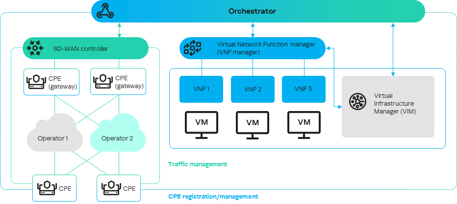
Architecture of Kaspersky SD-WAN
Page top