Contents
Managing virtual routing and forwarding (VRF) tables
Kaspersky SD-WAN supports the Virtual Routing and Forwarding (VRF) technology for creating virtual routing and forwarding tables on CPE devices. You can create up to 100 virtual routing and forwarding tables.
When creating a virtual routing and forwarding table, you must select network interfaces that you want to add to it. You cannot add the same network interface to multiple virtual routing and forwarding tables. Network interfaces for connecting the CPE device to the controller and orchestrator are automatically added to the default virtual routing and forwarding table and you cannot add them to other virtual routing and forwarding tables.
If network interfaces are added to different virtual routing and forwarding tables, networks connected to these network interfaces do not have access to each other. In this situation, network interfaces can have IP addresses from identical or overlapping subnets.
When you create a virtual routing and forwarding table, a system network interface corresponding to this virtual routing and forwarding table is automatically created on the CPE device. This system network interface is used to forward traffic between network interfaces in the virtual routing and forwarding table. For the system network interface to work, you need to create a record for it in the orchestrator web interface.
If no firewall zones are assigned to network interfaces in the virtual routing and forwarding table, you need to make sure that by default, the firewall of the CPE device accepts traffic packets forwarded between network interfaces and subnets. You can specify default actions when configuring the basic settings of the firewall.
If firewall zones are assigned to network interfaces in the virtual routing and forwarding table, and the CPE device firewall does not, by default, accept traffic packets forwarded between network interfaces and subnets, you must assign a firewall zone to the system network interface. The assigned firewall zone must also be assigned to one of the network interfaces in the virtual routing and forwarding table.
You can add BGP routes and static routes to virtual routing and forwarding tables of a CPE device. To add BGP routes to a virtual routing and forwarding table, specify that virtual routing and forwarding table when editing basic BGP settings. To add a static route to a virtual routing and forwarding table, specify that virtual routing and forwarding table when adding the static route.
You can use virtual routing and forwarding tables in the following scenarios:
- Network segmentation using virtual routing and forwarding tables
You can create virtual routing and forwarding tables to segment your network. In the figure below, network 1 is built between the 'overlay1' network interface and user PCs, and network 2 is built between the 'overlay2' network interface and ATMs. Both network interfaces are in the default virtual routing and forwarding table (default VRF), so the networks have access to each other and are insecure.
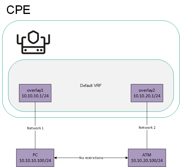
Network interfaces connected to different networks in the virtual default routing and forwarding table
To isolate networks 1 and 2, the overlay1 and overlay2 network interfaces must be added to different virtual routing and forwarding tables (VRF PC and VRF ATM), which creates two segments (see the figure below).
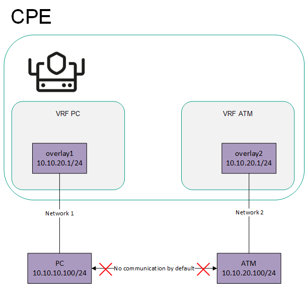
Network interfaces connected to different networks are in separate virtual default routing and forwarding tables
- Sending the 0.0.0.0/0 over BGP.
You can create a separate virtual routing and forwarding table for sending the 0.0.0.0/0 route between devices over BGP. The figure below shows a CPE device with the SD-WAN gateway role and a standard CPE device. All network interfaces of the CPE device are added to the default virtual routing and forwarding table (default VRF).
If the SD-WAN gateway sends the 0.0.0.0/0 BGP route from overlay network interface 10.10.10.254/24 to overlay network interface 10.10.10.1/24, such a route cannot be used. This is the case because the default virtual routing and forwarding table already has 0.0.0.0/0 routes with a lower administrative distance for connecting to the controller and orchestrator.
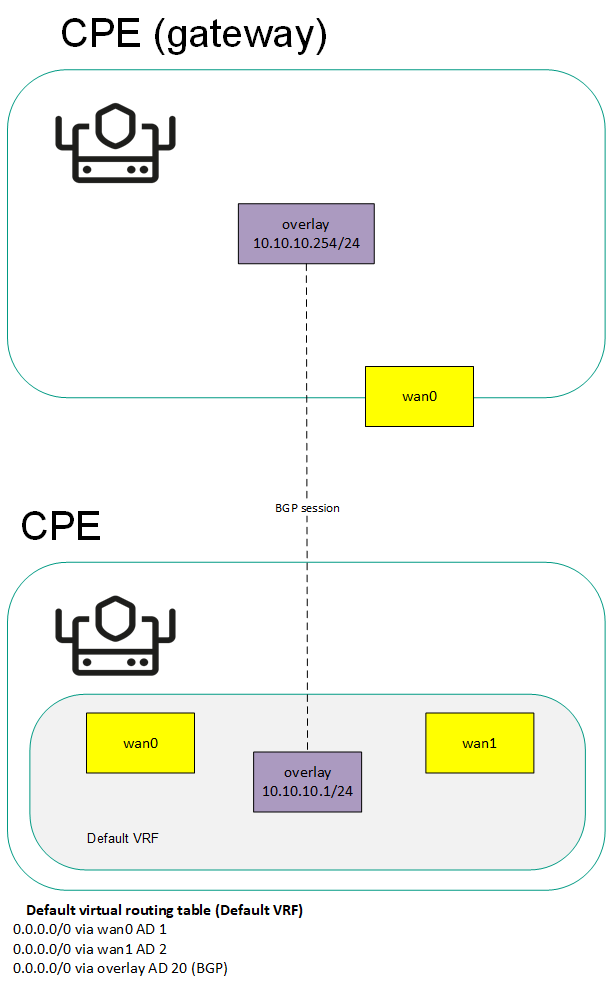
Sending the 0.0.0.0/0 route to a CPE device with the default virtual routing and forwarding table
To send route 0.0.0.0/0 over BGP through the overlay 10.10.10.254/24 network interface to overlay 10.10.10.1/24, you must create a separate virtual routing and forwarding table (VRF overlay) for the overlay 10.10.10.1/24 network interface and add BGP routes to it (see the figure below).
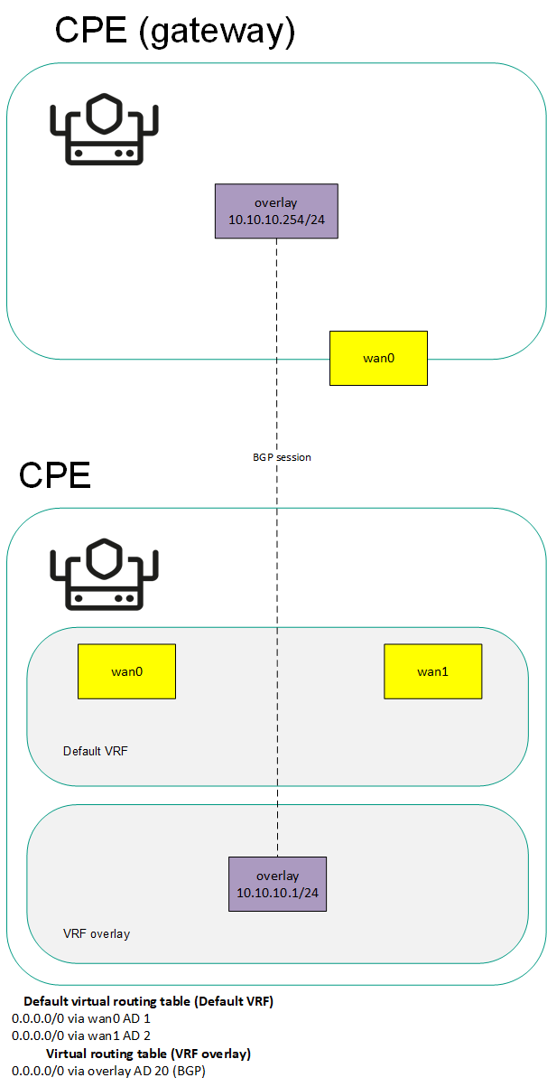
Sending the 0.0.0.0/0 route to a CPE device with a separate virtual routing and forwarding table for BGP routes
The table of virtual routing and forwarding tables is displayed in the CPE template and on the CPE device:
- To display the table of virtual routing and forwarding tables in a CPE template, go to the SD-WAN → CPE templates menu section, click the CPE template, and select the VRF tab.
- To display the table of virtual routing and forwarding tables on a CPE device, go to the SD-WAN → CPE menu section, click the CPE device, and select the VRF tab.
Information about virtual routing and forwarding tables is displayed in the following columns of the table:
- Name is the name of the virtual routing and forwarding table.
- Inherited indicates whether the virtual routing and forwarding table is inherited from CPE template:
- Yes
- No
This column is displayed only on the CPE device.
- Table is the ID of the virtual routing and forwarding table.
- Interfaces are network interfaces that have been added to the virtual routing and forwarding table.
Specifying core settings related to virtual routing tables
You can specify core settings related to virtual routing and forwarding tables in a CPE template or on a CPE device. This is necessary for correct operation of network services in virtual routing and forwarding tables created by you. Core settings specified in the CPE template are automatically propagated to all CPE devices that use this CPE template.
To specify core settings:
- Proceed to specify core settings in one of the following ways:
- If you want to edit core settings in a CPE template, go to the SD-WAN → CPE templates menu section, click the CPE template, and select the VRF → General settings tab.
- If you want to edit core settings on a CPE device, go to the SD-WAN → CPE menu section, click the CPE device, select the VRF → General settings tab, and select the Override check box.
Core settings are displayed.
- If necessary, do one of the following:
- If you want to use UDP network services in virtual routing and forwarding tables, select the UDP network services in all VRFs check box. This check box is cleared by default.
- If you want to use TCP network services in virtual routing and forwarding tables, select the TCP network services in all VRFs check box. This check box is cleared by default.
- If you do not want to use RAW sockets in virtual routing and forwarding tables, clear theRAW sockets in all VRFs check box. This check box is selected by default.
- In the upper part of the settings area, click Save to save the settings of the CPE template or CPE device.
Creating a virtual routing and forwarding table
You can create a virtual routing and forwarding table in a CPE template or on a CPE device. A virtual routing and forwarding table created in the CPE template is automatically created on all CPE devices that use this CPE template.
To create a virtual routing and forwarding table:
- Create a virtual routing and forwarding table in one of the following ways:
- If you want to create a virtual routing and forwarding table in a CPE template, go to the SD-WAN → CPE templates menu section, click the CPE template, and select the VRF tab.
- If you want to create a virtual routing and forwarding table on a CPE device, go to the SD-WAN → CPE menu section, click the CPE device, and select the VRF tab.
By default, the VRF tab is selected, which displays the table of virtual routing and forwarding tables.
- Click + VRF.
- This opens a window; in that window, in the Name field, enter the name of the virtual routing and forwarding table.
- In the Table field, enter the ID of the virtual routing and forwarding table. Range of values: 100 to 199.
- In the Interfaces drop-down list, select the created network interface that you want to add to the virtual routing and forwarding table. You cannot add the same network interface to multiple virtual routing and forwarding tables.
The network instance is added and displayed in the lower part of the window. You can add multiple network interfaces or delete network interfaces. To delete a network interface, click Delete next to it.
If you added a network interface with a name in the 'overlay.<number>' format (for example, 'overlay.100') to the virtual routing and forwarding table, you must select the Enable automatically and Force IP, route, and gateway check boxes when creating or editing the network interface.
- Click + Create.
The virtual routing and forwarding table is created and displayed in the table. A system network interface corresponding to the created virtual routing and forwarding table is created on the CPE device.
- Create a record in the orchestrator web interface for the system network interface:
- Select the Network tab.
The table of network interfaces is displayed.
- Click + Network interface.
- This opens a window; in that window, in the Alias field, enter the name of the virtual routing and forwarding table that you specified at step 3 of these instructions. The maximum length of the name is 15 characters.
- If firewall zones are assigned to network interfaces in the virtual routing and forwarding table, and the CPE device firewall does not, by default, accept traffic packets forwarded between network interfaces and subnets, in the Zone drop-down list, select a firewall zone. The selected firewall zone must also be assigned to one of the network interfaces in the virtual routing and forwarding table.
- In the Interface name field, enter the name of the virtual routing and forwarding table that you specified at step 3 of these instructions. The maximum length of the name is 256 characters.
- Select the Network tab.
- Click Create.
A record for the system network interface is created and displayed in the table.
- In the upper part of the settings area, click Save to save the settings of the CPE template or CPE device.
Modifying the virtual routing and forwarding table
You can edit a virtual routing and forwarding table in a CPE template or on a device. A virtual routing and forwarding table edited in the CPE template is automatically edited on all CPE devices that use this CPE template. You cannot edit a virtual routing and forwarding table that is inherited from a CPE template on a CPE device.
To edit a virtual routing and forwarding table:
- Edit a virtual routing and forwarding table in one of the following ways:
- If you want to edit a virtual routing and forwarding table in a CPE template, go to the SD-WAN → CPE templates menu section, click the CPE template, and select the VRF tab.
- If you want to edit a virtual routing and forwarding table on a CPE device, go to the SD-WAN → CPE menu section, click the CPE device, and select the VRF tab.
By default, the VRF tab is selected, which displays the table of virtual routing and forwarding tables.
- Click Edit next to the virtual routing and forwarding table that you want to edit.
- This opens a window; in that window, if necessary, edit the name and/or ID of the virtual routing and forwarding table, and add or delete network interfaces.
- Click Save.
The virtual routing and forwarding table is modified and updated in the table.
- In the upper part of the settings area, click Save to save the settings of the CPE template or CPE device.
Deleting a virtual routing and forwarding table
You can delete a virtual routing and forwarding table in a CPE template or on a CPE device. A virtual routing and forwarding table deleted in the CPE template is automatically deleted on all CPE devices that use this CPE template. You cannot delete a virtual routing and forwarding table that is inherited from a CPE template on a CPE device.
Deleted virtual routing and forwarding tables cannot be restored.
To delete a virtual routing and forwarding table:
- Delete a virtual routing and forwarding table in one of the following ways:
- If you want to delete a virtual routing and forwarding table in a CPE template, go to the SD-WAN → CPE templates menu section, click the CPE template, and select the VRF tab.
- If you want to delete a virtual routing and forwarding table on a CPE device, go to the SD-WAN → CPE menu section, click the CPE device, and select the VRF tab.
By default, the VRF tab is selected, which displays the table of virtual routing and forwarding tables.
- Click Delete next to the virtual routing and forwarding table that you want to delete.
- In the confirmation window, click Delete.
The virtual routing and forwarding table is deleted and is no longer displayed in the table.
- In the upper part of the settings area, click Save to save the settings of the CPE template or CPE device.