Contents
Managing links
You can view the links in one of the following ways:
- To display the table of links established from a CPE device, go to the SD-WAN → CPE menu section, click the CPE device, and select the Links tab.
- To display the table of all links, go to the Infrastructure menu section, click Management → Configuration menu next to the controller, and go to the Links section.
- To display the graphical topology with all links, go to the Infrastructure menu section, click Management → Configuration menu next to the controller, and go to the Topology section.
When viewing the table of links, information about the links is displayed in the following table columns:
- Source is the name, DPID, and OpenFlow port number of the CPE device that is the link source.
- Destination is the name, DPID, and OpenFlow port number of the CPE device that is the link destination.
- Last resort indicates whether the controller uses this link as the last resort when calculating the path, regardless of the monitoring indicators:
- Y
- N
- Thresholds monitoring indicates whether link monitoring is on:
- Y
- N
- CFM is the time interval for sending control packets when Connectivity Fault Management is running. This column displays two values in the <value 1>/<value 2> format:
- <value 1> is the time interval for sending control packets that you specified when you enabled CFM on the CPE device.
- <value 2> -is the time interval for sending control packets that is currently being used. One of the following time intervals can be used for sending control packets:
- The time interval for sending control packets that you specified when you enabled CFM on the CPE device. If you specify different time intervals for sending control packages on CPE devices, the largest of the specified time intervals is used. For example, if you specified 300 milliseconds as the control packet interval on CPE 1, and one second on CPE 2, the control packet interval is 1 second.
- The time interval for sending control packets that you specified when you enabled CFM on the link. The time interval for sending control packets set for the link overrides the time intervals for sending control packets set on CPE devices. For example, if you specified 300 milliseconds as the control packet interval on CPE 1, one second on CPE 2, and 10 seconds on the link between CPE 1 and CPE 2, the resulting time interval for sending control packets is 10 seconds.
Manually specified values in this column are underlined.
- MTU is the MTU value of the link.
- Errors/second is the number of errors per second on the link.
- Utilization (%) is the load of the link as a percentage of the bandwidth of the source service interface.
- Latency (ms.) is the delay time in milliseconds for traffic transmitted through the link.
- Jitter (ms.) is the jitter time in milliseconds for traffic transmitted through the link.
- Packet loss (%) is the percentage of traffic packet loss on the link.
- Speed (Mbit/sec.) is the speed of traffic transmission through the link in Mbps.
- Cost is the link cost.
The actions you can perform with the table are described in the Managing solution component tables instructions.
Specifying the cost of a link
To specify the cost of a link:
- Specify the link cost in one of the following ways:
- If you want to specify the cost of a link that was established from a CPE device, go to the SD-WAN → CPE section, click the CPE device, select the Links tab, and click Management → Set cost next to the link.
- If you want to specify the cost of one of the links in the table of all links, go to the Infrastructure section, click Management → Configuration menu next to the controller, go to the Links section, and click Management → Set cost next to the link.
- If you want to specify the cost of one of the links in the graphic topology with all links, go to the Infrastructure section, click Management → Configuration menu next to the controller, go to the Topology section, click the link, and click Set cost.
- This opens a window; in that window, select the Override check box to specify the cost of the link. This check box is cleared by default.
- In the Link cost field, enter the cost of the link. If you want to specify the same cost for the opposite-direction link, select the Save for both links check box. This check box is cleared by default.
- Click Save.
The link cost is specified.
- If you have specified the link cost for a link established from the CPE device, click Save in the upper part of the settings area to save the CPE device settings.
Enabling Dampening
Dampening is a configurable mechanism that excludes unstable links whose state changes too frequently from path calculation. When determining link instability, the following state changes are taken into account:
- UP/LIVE → DOWN/NOT-LIVE.
- DOWN/NOT-LIVE → UP/LIVE.
- UP/LIVE → UP/NOT-LIVE.
- UP/NOT-LIVE → UP/LIVE.
When Dampening is enabled on a link, each state change of the link increases the Penalty value. If the Penalty reaches the threshold within the specified time, access to the link is restricted (its cost is increased 10,000 times for the specified period of time). The value of each of these parameters is specified when you enable Dampening. By default, access to the link is resumed if the state of the link does not change for 10 minutes.
To enable Dampening:
- Enable Dampening in one of the following ways:
- If you want to enable Dampening for a link that was established from a CPE device, go to the SD-WAN → CPE section, click the CPE device, select the Links tab, and click Management → Dampening next to the link.
- If you want to enable Dampening for one of the links in the table of all links, go to the Infrastructure section, click Management → Configuration menu next to the controller, go to the Links section, and click Management → Dampening next to the link.
- If you want to enable Dampening for one of the links in the graphic topology with all links, go to the Infrastructure section, click Management → Configuration menu next to the controller, go to the Topology section, click the link, and click Dampening.
- This opens a window; in that window, select the Enable check box to enable Dampening on the link. This check box is cleared by default.
- In the Maximum suppress time (ms.) field, enter the time, in milliseconds, for which access to the link can be restricted. When the specified time elapses, all Dampening counters on the link are reset. Default value:
600000. - In the Penalty field, enter the number by which Penalty is incremented when the link changes state. Default value:
1. - In the Suppress threshold field, enter the Penalty value at which access to the link is restricted. Default value:
4. - In the Update interval (ms.) field, enter the time in milliseconds during which Penalty must attain the value specified in the Suppress threshold field for access to the link to be restricted. Default value:
120000. - If you want to view Dampening statistics for a link, click Load statistics.
- Click Save.
Dampening is enabled for the link.
- If you enabled Dampening for a link established from the CPE device, click Save in the upper part of the settings area to save the CPE device settings.
Enabling Forward Error Correction
The Forward Error Correction (FEC) functionality reduces the loss of traffic packets in links, especially for UDP applications, and the number of retransmissions, which lead to delays, and also recovers received data on the CPE device. Data recovery is provided by redundant encoding of the data stream on the device on the source CPE device.
If FEC is enabled on a link, the source CPE device encodes the traffic packet stream transmitted through the link and adds redundant traffic packets. Encoding on CPE devices may cause delays due to extra data processing.
The destination CPE device buffers traffic packets received through the link and decodes them, recovering lost traffic packets, if possible. We recommend using FEC on noisy links to reduce the packet loss and increase the speed of TCP connections. The general diagram of FEC is shown in the figure below.
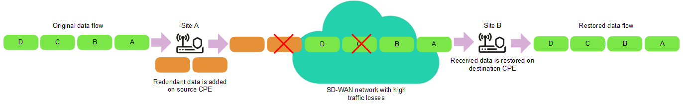
FEC diagram
To enable FEC:
- Enable FEC in one of the following ways:
- If you want to enable FEC for a link that was established from a CPE device, go to the SD-WAN → CPE section, click the CPE device, select the Links tab, and click Management → FEC/reordering next to the link.
- If you want to enable FEC for one of the links in the table of all links, go to the Infrastructure section, click Management → Configuration menu next to the controller, go to the Links section, and click Management → FEC/reordering next to the link.
- If you want to enable FEC for one of the links in the graphic topology with all links, go to the Infrastructure section, click Management → Configuration menu next to the controller, go to the Topology section, click the link, and click FEC/reordering.
- This opens a window; in that window, select the Override check box to enable FEC on the link. This check box is cleared by default.
- In the Redundancy ratio (original/redundant packet) drop-down list, select the ratio of original traffic packets to extra traffic packets with redundant code. Default value: 0:0 (FEC off) means FEC is not used. You can also specify the ratio of original traffic packets to redundant traffic packets by using the
topology.link.fec.ratiocontroller property. - In the Timeout field, enter the time, in milliseconds, during which a traffic packet can stay in the queue for FEC to apply. Range of values: 1 to 1000.
- Click Save.
FEC is enabled.
- If you enabled FEC for a link established from the CPE device, click Save in the upper part of the settings area to save the CPE device settings.
Determining the MTU value
You can determine the MTU value of a link to find out why fragmented packets are being blocked on the link (see the figure below).
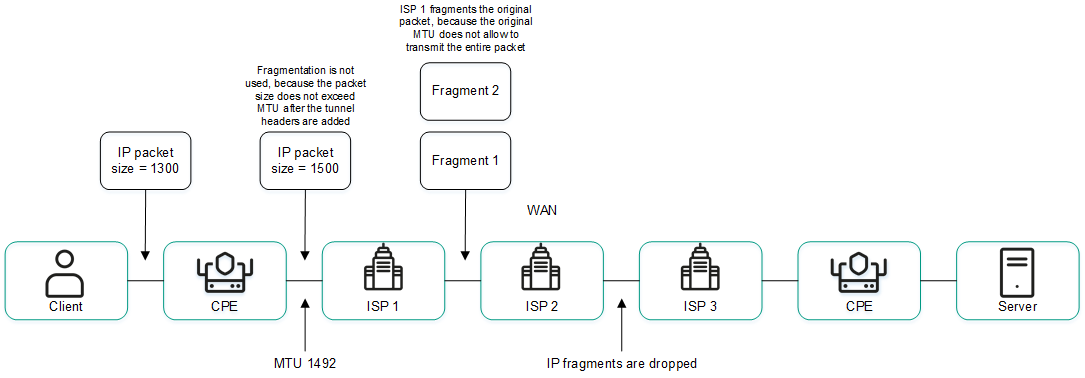
Links with a reduced MTU size and fragmented packet getting dropped
The MTU value is determined by sending LLDP packets with a variable payload size through the link. The minimum detectable MTU size is 1280 bytes, and the maximum is 1500 bytes. The MTU value is determined automatically when CPE devices are enabled and periodically at an interval specified in the topology.link.pmtud.scheduler.interval.sec controller property.
You can determine the MTU value manually.
To manually determine the MTU value,
Determine the MTU value in one of the following ways:
- If you want to manually determine the MTU value for a link that was established from a CPE device, go to the SD-WAN → CPE section, click the CPE device, select the Links tab, and click Management → Check MTU next to the link.
- If you want to manually determine the MTU value for one of the links in the table of all links, go to the Infrastructure section, click Management → Configuration menu next to the controller, go to the Links section, and click Management → Check MTU next to the link.
The MTU value is displayed in the MTU column.
Page topTraffic encryption
Traffic encryption is a mechanism of securing the exchange of traffic between CPE devices through links. For example, you can encrypt traffic that is transmitted over unsecured links.
Traffic encryption does not replace the need to use other information security measures, such as TLS, LDAPS, and other protocols that protect traffic within the overlay network.
The controller automatically generates keys for encrypting and decrypting traffic and sends the keys to CPE devices. Traffic is encrypted on the source CPE device using the encryption key. The destination CPE device decrypts the traffic using the decryption key.
The keys are regularly updated to deprive third parties of the opportunity to encrypt or decrypt the transmitted traffic if a key is intercepted. You can specify the length of time after which the keys are updated on CPE devices using the topology.link.encryption.key.update.interval.minutes controller property.
Traffic encryption is supported only on CPE devices running Kaspersky SD-WAN software.
You can enable traffic encryption on a CPE device or on a link. A CPE device with traffic encryption enabled forwards encrypted traffic over all of its links, including new links that will be established in the future. When traffic encryption is enabled on a link, the CPE device transmits encrypted traffic over that link. When traffic encryption is disabled, the keys generated by the controller for encrypting and decrypting traffic are deleted from all attached CPE devices. By default, traffic encryption is disabled on CPE devices and links.
For example, you can enable traffic encryption on a CPE device and disable traffic encryption on one of the links of that CPE device. In this case, the CPE device transmits encrypted traffic over all its links, except for the link on which traffic encryption is disabled.
Enabling traffic encryption on a CPE device
A CPE device with traffic encryption enabled forwards encrypted traffic over all of its links, including new links that will be established in the future. You can enable or disable traffic encryption in a CPE template or on a CPE device. Traffic encryption settings specified in the CPE template are automatically propagated to all CPE devices that use this CPE template.
To enable traffic encryption on a CPE device:
- Enable traffic encryption on the CPE device in one of the following ways:
- If you want to enable traffic encryption in a CPE template, go to the SD-WAN → CPE templates menu section, click the CPE template, and select the Link encryption tab.
- If you want to enable traffic encryption on a CPE device, go to the SD-WAN → CPE menu section, click the CPE device, select the Link encryption tab, and select the Override check box.
The traffic encryption policy is displayed.
- In the Enable encryption drop-down list, select Enabled. The default value is Disabled.
- In the upper part of the settings area, click Save to save the settings of the CPE template or CPE device.
Enabling traffic encryption on a link
When traffic encryption is enabled on a link, the CPE device transmits encrypted traffic over that link.
To enable encryption of traffic on a link:
- Enable traffic encryption on the link in one of the following ways:
- If you want to enable traffic encryption for a link that was established from a CPE device, go to the SD-WAN → CPE section, click the CPE device, select the Links tab, and click Management → Set encryption next to the link.
- If you want to enable traffic encryption for one of the links in the table of all links, go to the Infrastructure section, click Management → Configuration menu next to the controller, go to the Links section, and click Management → Set encryption next to the link.
- If you want to enable traffic encryption for one of the links in the graphic topology with all links, go to the Infrastructure section, click Management → Configuration menu next to the controller, go to the Topology section, click the link, and click Set encryption.
- This opens a window, in that window, select the Override check box. This check box is cleared by default.
- Select the Enable encryption check box to enable traffic encryption for the link. This check box is cleared by default.
- Click Save.
Traffic encryption is enabled on the link.
- If you enabled traffic encryption for a link established from the CPE device, click Save in the upper part of the settings area to save the CPE device settings.
Connectivity Fault Management (CFM)
The Connectivity Fault Management (hereinafter also CFM) functionality allows detecting unavailable links between CPE devices. When CFM is enabled, the CPE device sends Continuity Check Message (CCM) control packets over its links at the specified intervals, and listens for response control packets on opposite-direction links. If response control packets do not arrive, the CPE device considers the link unavailable and starts transmitting traffic over a randomly selected available link.
The response timeout is equal to the control packet sending interval times 3.5. The time it takes to switch a CPE device over to a new connection when no response packets are received is equal to the control packet sending interval multiplied by a number in the range from 3.5 to 7. For example, if you specified 300 milliseconds as the time interval for sending control packets, the response timeout is 1.05 seconds, and the time it takes to switch the CPE device to a new link is 1.05 to 2.1 seconds.
You can enable CFM on a CPE device or link:
- A CPE device with CFM enabled sends control packets over all of its links, including new links that will be established in the future. If you specify different time intervals for sending control packages on CPE devices, the largest of the specified time intervals is used. For example, if you specified 300 milliseconds as the control packet interval on CPE 1, and 1 second on CPE 2, the control packet interval is 1 second.
When CFM is enabled on one CPE device and disabled on the other CPE device, the CPE device with CFM enabled takes precedence. In this case, CPE devices send control packets to each other over all of their links.
- When CFM is enabled for a link, the CPE device sends control packets over that link only. When you enable CFM for a link, you must also enable CFM on the opposite-direction link. The time interval for sending control packets set for the link overrides the time intervals for sending control packets set on CPE devices. For example, if you specified 300 milliseconds as the control packet interval on CPE 1, 1 second on CPE 2, and 10 seconds on the link between CPE 1 and CPE 2, the resulting time interval for sending control packets is 10 seconds.
For example, you can enable CFM on a CPE device and disable CFM on one of the links of that CPE device. In this case, the CPE device sends control packets over all its links, except for the link on which CFM is disabled. By default, CFM is disabled on CPE devices and links.
Enabling CFM on a CPE device
A CPE device with CFM enabled sends control packets over all of its links, including new links that will be established in the future. You can enable or disable CFM in a CPE template or on a CPE device. CFM settings specified in the CPE template are automatically propagated to all CPE devices that use this CPE template.
When CFM is enabled on one CPE device and disabled on the other CPE device, the CPE device with CFM enabled takes precedence. In this case, CPE devices send control packets to each other over all of their links.
To enable CFM on a CPE device:
- Enable CFM on the CPE device in one of the following ways:
- If you want to enable CFM in a CPE template, go to the SD-WAN → CPE templates menu section, click the CPE template, and select the CFM tab.
- If you want to enable CFM on a CPE device, go to the SD-WAN → CPE menu section, click the CPE device, select the CFM tab, and select the Override check box.
- In the CFM drop-down list, select Enabled. The default value is Disabled.
- In the Interval drop-down list, select the time interval for sending control packets:
- 300 ms.
- 1 s. Default value.
- 10 s.
- 1 min.
The response timeout is equal to the control packet sending interval times 3.5. The time it takes to switch a CPE device over to a new connection when no response packets are received is equal to the control packet sending interval multiplied by a number in the range from 3.5 to 7. For example, if in the Interval drop-down list, you selected 300 ms, the response timeout is 1.05 seconds, and the time it takes to switch the CPE device to a new link is 1.05 to 2.1 seconds.
If you specified different control packet intervals on CPE devices, the largest of the specified intervals is used. For example, if in the Interval drop-down list for CPE 1, you selected 300 ms, and for CPE 2 you selected 1 s, the time interval for sending control packets is 1 second.
- In the upper part of the settings area, click Save to save the settings of the CPE template or CPE device.
Enabling CFM on a link
When CFM is enabled for a link, the CPE device sends control packets over that link only. When you enable CFM for a link, you must also enable CFM on the opposite-direction link.
To enable CFM on a link:
- Enable CFM on the link in one of the following ways:
- If you want to enable CFM for a link that was established from a CPE device, go to the SD-WAN → CPE section, click the CPE device, select the Links tab, and click Management → Set CFM next to the link.
- If you want to enable CFM for one of the links in the table of all links, go to the Infrastructure section, click Management → Configuration menu next to the controller, go to the Links section, and click Management → Set CFM next to the link.
- If you want to enable CFM for one of the links in the graphic topology with all links, go to the Infrastructure section, click Management → Configuration menu next to the controller, go to the Topology section, click the link, and click Set CFM.
- This opens a window, in that window, select the Override check box. This check box is cleared by default.
- Select Save for both links to enable CFM on the opposite-direction link. This check box is cleared by default.
- In the CFM drop-down list, select Enabled. The default value is Disabled.
- In the Interval drop-down list, select the time interval for sending control packets:
- 300 ms.
- 1 s. Default value.
- 10 s.
- 1 min.
The response timeout is equal to the control packet sending interval times 3.5. The time it takes to switch a CPE device over to a new connection when no response packets are received is equal to the control packet sending interval multiplied by a number in the range from 3.5 to 7. For example, if in the Interval drop-down list, you selected 300 ms, the response timeout is 1.05 seconds, and the time it takes to switch the CPE device to a new link is 1.05 to 2.1 seconds.
The time interval for sending control packets set for the link overrides the time intervals for sending control packets that you specified when enabling CFM on CPE devices. For example, if in the Interval drop-down list for CPE 1, you selected 300 ms, for CPE 2 you selected 1 s, and for the link between CPE 1 and CPE 2 you selected 10 s, the resulting time interval for sending control packets is 10 seconds.
- Click Save.
CFM is enabled for the link.
- If you enabled CFM for a link established from the CPE device, click Save in the upper part of the settings area to save the CPE device settings.