Contents
- Managing CPE devices
- Composition of CPE devices
- Composition of uCPE devices
- SD-WAN managementTunnel management transport service
- Automatic configuration of CPE (ZTP) devices
- CPE device statuses and states
- Ensuring connectivity of CPE devices with SD-WAN Controllers
- Automatically updating the link cost based on maximum speed of the interface
- CPE template
- Creating a CPE device
- Specifying the address of a CPE device
- Registering a CPE device
- Activating or deactivating a CPE device
- Using a web address to activate a CPE device
- Connecting to the CPE device console
- Deleting a CPE device
- Viewing the password of a CPE device
- Restarting a CPE device
- Shutting down a CPE device
- Exporting settings and SD-WAN interfaces from a CPE device
- Exporting network interfaces from a CPE device
- Searching for CPE devices
- Automatic removal and deactivation of a CPE device
- Two-factor authentication of a CPE device
- Orchestrator certificates
- Tags
- Out-of-band management of CPE devices
- Managing CPE devices in SD-WAN controller menu
- Viewing the OpenFlow table of a CPE device
- Viewing statistics of OpenFlow interfaces
- Viewing statistics of queues on LAN interfaces
- Navigating to service interfaces on a CPE device
- Viewing the specifications of a CPE device
- Viewing the usage of a CPE device
- Changing the status of a CPE device in the SD-WAN Controller
- Changing the MAC address of a CPE device
- Terminating the TCP session between a CPE device and the SD-WAN Controller
- Scripts
- Network interfaces
- Configuring the connection of a CPE device to the SD-WAN network
- SD-WAN interfaces
- OpenFlow interfaces
- Service interfaces and UNIs
- Creating a service interface
- Creating an ACL interface
- Viewing the usage of a service interface and an ACL interface
- Deleting a service interface and an ACL interface
- Creating a UNI template
- Creating a UNI in a template
- Editing a UNI in a template
- Deleting a UNI in a template
- Deleting a UNI template
- Creating a UNI
- Editing a UNI
- Deleting a UNI
- Filtering routes
- The BGP dynamic routing protocol
- The OSPF dynamic routing protocol
- The BFD protocol
- Creating or deleting a static IPv4 route
- The VRRP protocol
- Viewing the settings of the CPE device connection to the service provider network
- Configuring the connection of a CPE device to a Syslog server
- Configuring the connection of a CPE device to an NTP server
- Firmware
Managing CPE devices
Kaspersky SD-WAN lets you install CPE devices with the following technical characteristics at your organization's branches or client locations:
- Standard CPU architecture:
- x86 (Intel 80x86)
- Arm v8/64 (Advanced RISC Machine)
- MIPS (Microprocessor without Interlocked Pipeline Stages)
- No vendor lock-in
- Minimal hardware requirements, such as CPU and RAM
Connected CPE devices are automatically registered in the inventory database and have direct internet access (DIA). You can use two types of CPE devices:
- — to provide additional from the data center or cloud, you must make the virtual CPE device part of the service chain. After providing the VNF, traffic is sent to its destination.
- (hereinafter also uCPE) — hosting VNFs locally improves response times, optimizes transport streams, and lets you manage these VNFs through the orchestrator web interface.
Composition of CPE devices
CPE devices have the following external interfaces:
- One or more LAN interfaces. You can combine LAN interfaces to form a switch using Linux bridges. In this way, you can improve the speed of data transmission to network devices connected to the switch, optimize the use of network resources and prevent bottlenecks.
If one of the interfaces fails, traffic can be moved to another interface that remains operational. Aggregating interfaces into a single switch also makes it easier to scale your network because you can add new interfaces to the switch as needed.
- One or more WAN interfaces. These interfaces can be wired or wireless.
Each CPE device has an OpenFlow software switch (virtual switch, hereinafter also referred to as softswitch), which is managed by the
and, by default, has interfaces with the following numbers:- 1 (ovs-mgmt) — provides internal network management and configuration of the CPE device through the SD-WAN managementTunnel transport service after connecting to the and SD-WAN Controller.
- 2 (ovs-lan) — provides a connection to a Linux bridge.
- 4800–4803 — GENEVE interfaces created for each WAN interface of the SD-WAN. The first GENEVE interface has the number 4800. Other GENEVE interfaces are assigned consecutive numbers. For example, the second GENEVE interface is assigned the number 4801.
As the source IP address, you must assign the IP address of the corresponding WAN interface. As the destination interface, you must assign the GENEVE interface number.
After the CPE device receives the parameters of WAN interfaces, a separate routing table is created for each WAN interface.
The figure below shows the logic diagram of a CPE device.
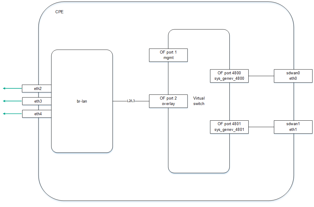
Logic diagram of a CPE device
Composition of uCPE devices
An uCPE device additionally supports deploying VNFs (as in a virtual data center infrastructure). The uCPE software must be installed on an x86 server. Each such device includes a hypervisor and VIM (OpenStack in minimal configuration). The rest of components required for VNF orchestration are located in the data center. The softswitch on the uCPE device has an additional OS-data interface.
The orchestrator begins interacting with the
on the uCPE device after the device registers itself and connects to the SD-WAN managementTunnel transport service.You can create a network service on a uCPE device that is in the Disconnected state. In this case, the orchestrator monitors the availability of the uCPE device and creates a network service when the VIM begins responding to API requests.
The VIM on the uCPE device is assigned by default to the
for which the SD-WAN instance is deployed, but you can select a different tenant.When creating a network service, you must select a VIM for VNF deployment. You can select a VIM in the data center that which is associated with the tenant, or a VIM on the uCPE device. If you remove a uCPE device, all service chains deployed on that device are deleted.
The figure below shows the logic diagram of a uCPE device.
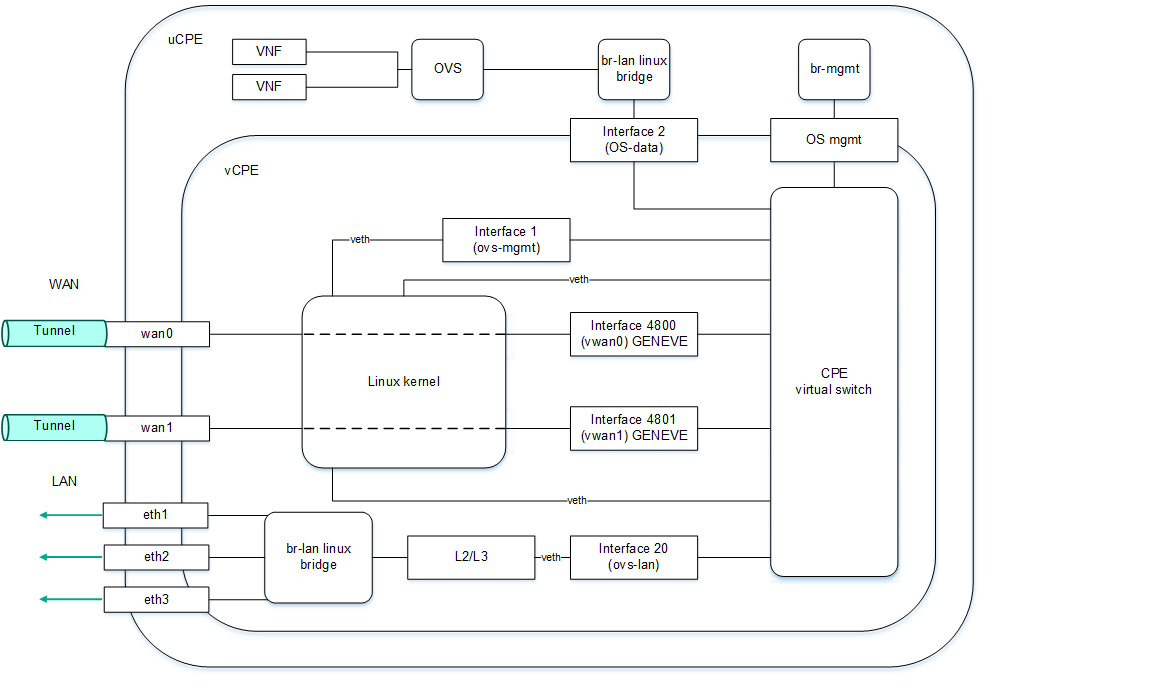
Logic diagram of a uCPE device
SD-WAN managementTunnel management transport service
Kaspersky SD-WAN uses the SD-WAN managementTunnel P2M transport service for managing and monitoring CPE devices. The root interfaces of this transport service are the service interfaces on one or more CPE devices behind which are the
components.After a CPE device connects to an SD-WAN Controller, a service interface with the Access encapsulation type is automatically created on top of the ovs-mgmt OpenFlow interface. The orchestrator activates the CPE device and adds this service interface to the SD-WAN managementTunnel management transport service with the Leaf role (see the figure below).
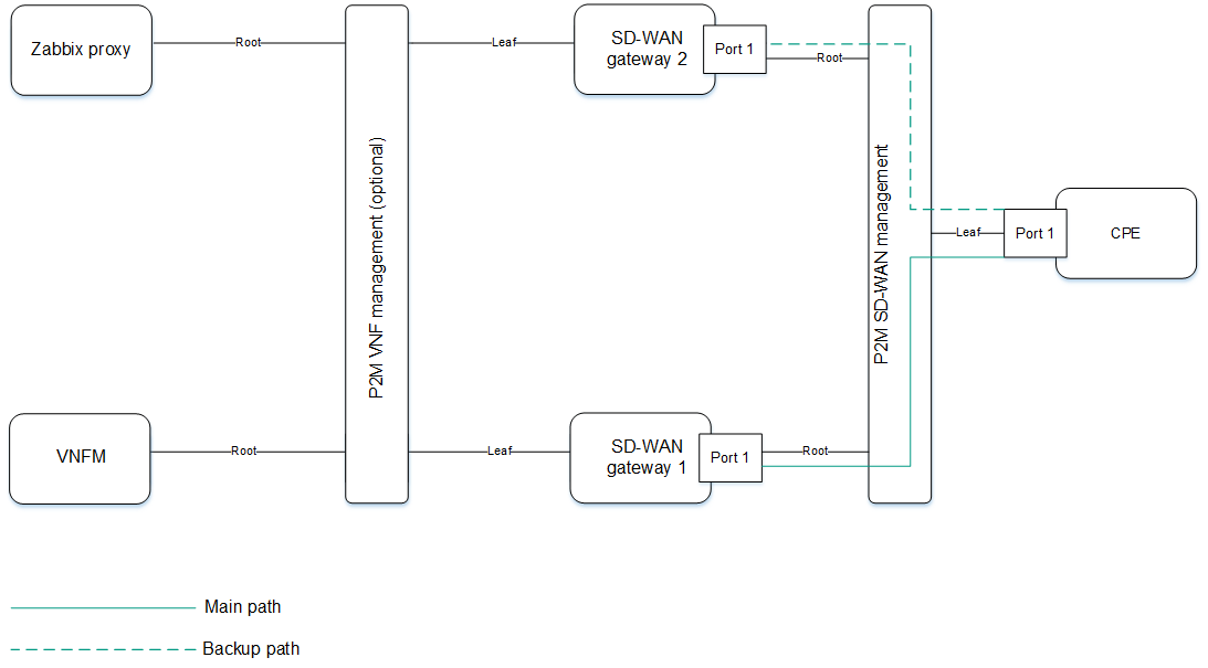
CPE device management transport service
The IP address for managing the CPE device is determined automatically from the pool of addresses configured by you. When a CPE device is deleted, the IP address associated with it is returned to the address pool. The VNF and PNF components communicate with each other and with the orchestrator using public IP addresses.
You can provide access to the web console of the CPE device and configure an SSH connection to the console using a CPE template. Note that to do this, you do not need to configure IP connectivity with the device.
provides access to the device console through the SD-WAN managementTunnel transport service. Page topAutomatic configuration of CPE (ZTP) devices
Each CPE device has a unique DPID (Datapath Identifier). It is a 64-bit number that is generated based on a unique characteristic of the CPE device, such as the MAC address of the WAN0 interface or a serial number.
To use a CPE device, you must first create an entry for it in the web interface, and then connect the device itself to the orchestrator. Alternatively, you can connect the device to the orchestrator (in this case, it is displayed in the web interface with the Unknown status) and then create an entry. In both cases, the entry is associated with the device based on its DPID.
Two main scenarios exist for registering CPE devices: Zero Touch Provisioning (ZTP) or with additional configuration. Additional configuration includes, for example, assigning static IP addresses and creating routes, uploading security certificates, and generating tokens.
The CPE device is configured as follows:
- If additional configuration is needed, URL activation is used.
- The CPE device receives IP addresses of WAN interfaces and DNS servers as well as default routes from the service provider via DHCP.
- The CPE device uses the FQDN or IP address of the orchestrator to connect to it, passes its own DPID, and obtains the public IP addresses of the SD-WAN Controller and SD-WAN gateways (if any). Certificates are also uploaded to the CPE device.
- The CPE device establishes a TLS connection with the SD-WAN controller over the IP network using the service provider's network or the internet.
- The SD-WAN Controller programs the CPE device to create links from each WAN interface.
To automatically configure a CPE device over the internet, you must configure public IP addresses of the orchestrator, controller, and SD-WAN gateways. NAT is supported for the following interfaces as an alternative to public IP addresses:
- tcp 443, 81 for the orchestrator
- tcp 6653 to 6656 for the SD-WAN Controller
- udp 4800 to 4803 for SD-WAN gateways
CPE device statuses and states
CPE devices can have the following statuses:
- Unknown means that the device is connected to the orchestrator, but an entry was not created for it in the web interface.
- Waiting means that an entry was created for the device in the web interface, but the device is not connected to the orchestrator and/or is not registered.
- Registering means that the device is in the process of registration.
- Error means that an error occurred during the registration of the device.
- Registered means that the device has been registered successfully.
- Configuration means that the configuration of the device is being modified.
CPE devices can be in the following states:
- In relation to the orchestrator:
- Activated means that the configuration of the assigned template has been applied to the device. You can connect such a device to transport services and use it to transmit traffic.
- Deactivated (in the Waiting status) means that the configuration of the assigned template has not been applied to the device. You can make local changes to the device configuration before activating it.
- Deactivated (in the Registered status) means that the device is blocked from transmitting traffic through the links and the orchestrator does not respond to requests coming from the device.
- In relation to the SD-WAN Controller:
- Active means that the device is being managed by a Controller.
- Inactive means that the device is not being managed by a Controller.
Ensuring connectivity of CPE devices with SD-WAN Controllers
CPE devices establish a connection with SD-WAN Controllers via the OpenFlow protocol in the control plane through all WAN interfaces: a TCP session is established with all SD-WAN Controllers through each WAN interface of the CPE device.
The diagram below shows the principle of establishing connections between a CPE device and SD-WAN Controllers.
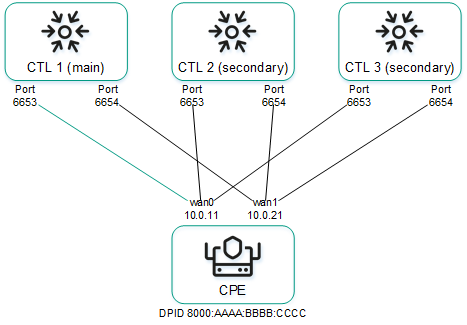
Establishing connections between SD-WAN Controllers and a CPE device
In the example above, in a cluster of three controllers and a CPE device six TCP sessions are established with two WAN interfaces:
- 10.0.1.1 → ctl1:6653
- 10.0.2.1 → ctl1:6654
- 10.0.1.1 → ctl2:6653
- 10.0.2.1 → ctl2:6654
- 10.0.1.1 → ctl3:6653
- 10.0.2.1 → ctl3:6654
Only one session is a primary session at any given time. The parameters for switching and restoring the main session are specified when configuring the connection of the CPE device to the SD-WAN network.
Page topAutomatically updating the link cost based on maximum speed of the interface
If the speed of the WAN interface of the SD-WAN on the CPE device is higher than the network speed provided by the service provider, you must limit the maximum speed of that interface to match the network speed.
Example: The service provider gives the client Internet access at a speed of 50 Mbps and the speed of the physical connection at the CPE device interface is 100 Mbps. In this case, for correct calculation of link cost and QoS, you must specify the maximum speed value of 50. |
The link cost value is calculated based on the maximum speed parameter. The relation of the maximum speed and cost parameters is as follows:
- Maximum rate specifies the maximum interface bandwidth for correctly calculating logical queues for QoS. Measured in Mbps (megabits per second).
- Cost determines the weight of the interface in the topology and is calculated using the formula:
Cost = 10,000,000 / Speed, whereSpeedis equal to the maximum speed value. The lower the cost value, the higher the priority of the link in the network topology.
When the maximum speed changes, the cost value changes for links in both directions. The lowest maximum speed value of the interfaces participating in the link is taken for the link.
You can manually specify the link cost as well as the maximum speed of the SD-WAN interface when creating it.
Page topCPE template
A CPE template contains the configuration of a CPE device. You can configure a template once and then apply it to the devices you create. This way you avoid the need to configure each device individually.
Note that certain CPE device settings can only be set in a template. For example, the template specifies the port number that the device uses to connect to the orchestrator. This setting cannot be changed on an individual device.
When you make changes to a CPE template, they are automatically applied to all devices that are using that template. After you finish managing the CPE template, you can proceed to create and configure individual devices. The device is configured in accordance with the applied template, but you can make local changes if not all settings meet your requirements.
Creating a CPE template
To create a CPE template:
- In the menu, go to the SD-WAN section.
By default, the CPE subsection is displayed with a table of CPE devices.
- In the upper part of the page, click + CPE template.
- This opens a window; in that window, in the Name field, enter the name of the CPE template.
- In the Type drop-down list, select the CPE template type:
- CPE for a standard CPE device template. This is the default setting.
- uCPE for a uCPE device template.
- Click Create.
The CPE templates subsection is displayed with a table of CPE devices. The template is created and displayed in the table. You can now apply it to a CPE device when creating that device.
Page topExporting a CPE template
You can export a CPE template configuration and then import it into another template.
To export a CPE template:
- In the menu, go to the SD-WAN → CPE templates subsection.
A table of CPE templates is displayed.
- Click the CPE template.
The settings area is displayed in the lower part of the page. You can expand the settings area to fill the entire page by clicking the expand button
 .
. - In the upper part of the settings area, under Actions click Export.
An archive in the TAR.GZ format is saved on your local device.
The archive contains the following data:
- File with the description of the CPE template in XML format
- Script files
- Files required to run scripts, such as SSL certificates
The entire configuration is exported, including all settings specified on template tabs.
The saved configuration archive does not contain information about devices to which the original CPE template was applied.
Page topImporting a CPE template
When a CPE template is imported into another template, their configurations become identical. During import, you can select the tabs of the CPE template on which you want to keep the original configuration.
Before importing a CPE template, you must export a CPE template.
After the import, the CPE template remains applied to devices, but the configuration of those devices is not changed.
To import a CPE template:
- In the menu, go to the SD-WAN → CPE templates subsection.
A table of CPE templates is displayed.
- Click the CPE template.
The settings area is displayed in the lower part of the page. You can expand the settings area to fill the entire page by clicking the expand button
. - In the upper part of the settings area, under Actions click Import.
- This opens a window; in that window, clear the check boxes next to the CPE template tabs that you want to leave unchanged after import.
- In the File field, specify the path to the TAR.GZ archive.
- Click Import.
The configuration of the CPE template is changed to match the imported template.
Page topCloning a CPE template
When a CPE template is cloned, a copy of the template with a new name is created; this copy is initially not applied to any devices.
To clone a CPE template:
- In the menu, go to the SD-WAN → CPE templates subsection.
A table of CPE templates is displayed.
- Click the CPE template.
The settings area is displayed in the lower part of the page. You can expand the settings area to fill the entire page by clicking the expand button
. - In the upper part of the settings area, under Actions click Clone.
- This opens a window; in that window, enter the name of the new CPE template.
- Click Clone.
A copy of the CPE template is created and displayed in the table.
Page topExporting settings and SD-WAN interfaces from a CPE template
From a CPE template, you can export the settings for connecting the device to the SD-WAN network, which are configured on the SD-WAN settings tab, as well as the configuration of SD-WAN interfaces that are configured on the SD-WAN settings → Interfaces tab.
To export settings and SD-WAN interfaces from a CPE template:
- In the menu, go to the SD-WAN → CPE templates subsection.
A table of CPE templates is displayed.
- Click the CPE template.
The settings area is displayed in the lower part of the page. You can expand the settings area to fill the entire page by clicking the expand button
. - In the upper part of the settings area, under Actions click Export SD-WAN settings.
A JSON file named <Template name>sdwan-config is saved to your local device.
Page topExporting network interfaces from a CPE template
From the CPE template, you can export the configuration of network interfaces, which are configured on the Network settings tab.
To export network interfaces from a CPE template:
- In the menu, go to the SD-WAN → CPE templates subsection.
A table of CPE templates is displayed.
- Click the CPE template.
The settings area is displayed in the lower part of the page. You can expand the settings area to fill the entire page by clicking the expand button
. - In the upper part of the settings area, under Actions click Export network interfaces.
A file in JSON format with the name <Template name>-network-config is saved to your local device.
Page topViewing devices that are using a CPE template
To view devices that are using a CPE template:
- In the menu, go to the SD-WAN → CPE templates subsection.
A table of CPE templates is displayed.
- Click the CPE template.
The settings area is displayed in the lower part of the page. You can expand the settings area to fill the entire page by clicking the expand button
. - In the upper part of the settings area, under Actions click Show associated CPEs.
The CPE subsection is displayed with a table of CPE devices. Only devices that are using the CPE template are listed in the table.
Page topDeleting a CPE template
You cannot delete a template that is currently applied to CPE devices. Deleted templates cannot be restored.
To delete a CPE template:
- In the menu, go to the SD-WAN → CPE templates subsection.
A table of CPE templates is displayed.
- Click the CPE template.
The settings area is displayed in the lower part of the page. You can expand the settings area to fill the entire page by clicking the expand button
. - In the upper part of the settings area, under Actions click Delete.
- In the confirmation window, click Delete.
The CPE template is deleted and is no longer displayed in the table.
Page topCreating a CPE device
Before connecting a CPE device to the orchestrator, you can create an entry for it in the web interface. When creating an entry, you must specify the DPID to subsequently map it to the connected device. When an entry is successfully mapped to a device, it is automatically registered.
You can create a CPE device for the current SD-WAN instance, as well as for a selected tenant or SD-WAN instance. To create a CPE device, use the following instructions:
- Creating a CPE device for the current SD-WAN instance.
- Creating a CPE device for a tenant.
- Creating a CPE device for an SD-WAN instance.
To create a CPE device for an SD-WAN instance:
- In the menu, go to the SD-WAN → SD-WAN instances subsection.
A table of SD-WAN instances is displayed.
- Click the relevant SD-WAN instance.
The settings area is displayed in the lower part of the page. You can expand the settings area to fill the entire page by clicking the expand button
. - In the upper part of the settings area, click CPE.
- This opens a window; in that window, in the Name field, enter the name of the CPE device.
- In the DPID field, enter the DPID of the CPE device.
- In the State drop-down list, select the device state after registration:
- Activated to apply the configuration of the CPE template to the device. An activated device can be connected to transport services and used to transmit traffic. This is the default setting.
- Deactivated to not apply the configuration of the CPE template to the device. You can make local changes to the device configuration before activating it.
- If necessary, enter a brief description of the device in the Description field.
- Under Tenant, select the main tenant. You can select a pool of SD-WAN instances or an individual instance from the pool.
- If necessary, in the Customer tenant section, select a tenant for your client's organization.
- If necessary, in the UNI template section, select an UNI template to create the UNIs contained in the template on the device.
- Under CPE template, select a CPE template to configure the device in accordance with the configuration of that template.
- Click Next and specify the address of the CPE device location in the Address field. As you enter the address, you are prompted to select an address from a drop-down list.
The address is displayed on the map.
- Click Create.
The web interface of the SD-WAN instance is opened in a new browser tab and you are authenticated as an administrator. By default, the CPE subsection is displayed with a table of CPE devices. The device is created and displayed in the table. Now you can configure and use it for traffic transmission.
- In the menu, go to the SD-WAN → SD-WAN instances subsection.
Specifying the address of a CPE device
To specify the address of a CPE device:
- In the menu, go to the SD-WAN section.
By default, the CPE subsection is displayed with a table of CPE devices.
- Click the CPE device.
The settings area is displayed in the lower part of the page. You can expand the settings area to fill the entire page by clicking the expand button
. - In the upper part of the settings area, under Actions click Set location.
- This opens a window; in that window, enter the address of the CPE device's location. As you enter the address, you are prompted to select an address from a drop-down list.
The address is displayed on the map.
- Click Save.
Registering a CPE device
If a CPE device connects to the orchestrator and cannot be mapped to any of entries you created, the device must be registered. When registering a CPE device, connecting to the vendor's cloud services is not necessary.
To register a CPE device:
- In the menu, go to the SD-WAN section.
By default, the CPE subsection is displayed with a table of CPE devices.
- Click the CPE device.
The settings area is displayed in the lower part of the page. You can expand the settings area to fill the entire page by clicking the expand button
. - In the upper part of the settings area, under Actions click Register.
- In the State drop-down list, select the device state after registration:
- Activated to apply the configuration of the CPE template to the device. An activated device can be connected to transport services and used to transmit traffic. This is the default setting.
- Deactivated to not apply the configuration of the CPE template to the device. You can make local changes to the device configuration before activating it.
- If necessary, enter a brief description of the device in the Description field.
- Under Tenant, select the main tenant. You can select a pool of SD-WAN instances or an individual instance from the pool.
- If necessary, in the Customer tenant section, select a tenant for your client's organization.
- If necessary, in the UNI template section, select an UNI template to create the UNIs contained in the template on the device.
- Under CPE template, select a CPE template to configure the device in accordance with the configuration of that template.
- Click Next and specify the address of the CPE device location in the Address field. As you enter the address, you are prompted to select an address from a drop-down list.
The address is displayed on the map.
- Click Register.
The CPE device status changes first to Registering, then to Registered.
Your subsequent actions depend on the value selected in the State drop-down list:
- If you selected Activated, you can use the device to relay traffic.
- If you selected Deactivated, you must configure the device, then activate it, and only then can you use it to transmit traffic.
Activating or deactivating a CPE device
When a device is activated, the CPE template is applied to it. A device that is not activated cannot be used for traffic transmission.
To activate or deactivate a CPE device:
- In the menu, go to the SD-WAN section.
By default, the CPE subsection is displayed with a table of CPE devices.
- Click the CPE device.
The settings area is displayed in the lower part of the page. You can expand the settings area to fill the entire page by clicking the expand button
. - In the upper part of the settings area, under Actions click Activate or Deactivate.
Using a web address to activate a CPE device
Kaspersky SD-WAN supports activation of CPE devices using a web address (URL-based ZTP). Activation using a web address simplifies and speeds up initial configuration of the CPE by automating the passing of settings in a web address and then applying the configuration.
By minimizing manual intervention, web address based activation reduces the qualification requirements for personnel that activates and configures the CPE device on location. This activation method is convenient for two-factor authentication or the initial application of basic network connectivity settings for connecting a CPE device to the orchestrator (for example, static IP or BGP).
The following special considerations apply to web address activation:
- Web address activation is available for CPE devices with firmware in the initial condition.
- CPE devices must not have the Unknown status.
You can specify the web address template for activation when configuring the CPE device connection to the SD-WAN network in the URL ZTP field.
To activate a CPE device using a web address:
- In the menu, go to the SD-WAN section.
By default, the CPE subsection is displayed with a table of CPE devices.
- Click the CPE device.
The settings area is displayed in the lower part of the page. You can expand the settings area to fill the entire page by clicking the expand button
. - In the upper part of the settings area, under Actions, click Get activation URL, and in the displayed window, copy the web address.
- Send the web address to the user who will activate and configure the CPE device on location. The user must complete the following steps to activate the CPE device:
- Connect to the LAN interface of the CPE device and obtain an IP address via DHCP.
- Follow the link received or paste the web address into the address bar of the browser.
- Wait for the CPE device to receive the configuration, apply the received settings and restart.
Connecting to the CPE device console
To connect to the console of a CPE device:
- In the menu, go to the SD-WAN section.
By default, the CPE subsection is displayed with a table of CPE devices.
- Click the CPE device.
The settings area is displayed in the lower part of the page. You can expand the settings area to fill the entire page by clicking the expand button
. - Under Actions, click Open SSH console.
This opens a console window in a new browser tab.
Page topDeleting a CPE device
When you delete a CPE device, all service interfaces created on the device are automatically deleted. Deleted CPE devices cannot be restored.
To delete a CPE device:
- In the menu, go to the SD-WAN section.
By default, the CPE subsection is displayed with a table of CPE devices.
- Click the CPE device.
The settings area is displayed in the lower part of the page. You can expand the settings area to fill the entire page by clicking the expand button
. - In the upper part of the settings area, under Actions click Delete.
- In the confirmation window, click Delete.
The CPE device is deleted and is no longer displayed in the table.
Page topViewing the password of a CPE device
To view the password of a CPE device:
- In the menu, go to the SD-WAN section.
By default, the CPE subsection is displayed with a table of CPE devices.
- Click the CPE device.
The settings area is displayed in the lower part of the page. You can expand the settings area to fill the entire page by clicking the expand button
. - In the upper part of the settings area, under Actions click Show password.
This opens a window with the CPE device password.
Page topRestarting a CPE device
To restart a CPE device:
- In the menu, go to the SD-WAN section.
By default, the CPE subsection is displayed with a table of CPE devices.
- Click the CPE device.
The settings area is displayed in the lower part of the page. You can expand the settings area to fill the entire page by clicking the expand button
. - In the upper part of the settings area, under Actions, click Reboot.
- In the confirmation window, click Reboot.
Shutting down a CPE device
A CPE device is shut down by sending the shutdown command to its operating system.
To shut down a CPE device:
- In the menu, go to the SD-WAN section.
By default, the CPE subsection is displayed with a table of CPE devices.
- Click the CPE device.
The settings area is displayed in the lower part of the page. You can expand the settings area to fill the entire page by clicking the expand button
. - In the upper part of the settings area, under Actions, click Shutdown.
- In the confirmation window, click Shutdown.
Exporting settings and SD-WAN interfaces from a CPE device
From a CPE device, you can export the settings for connecting the device to the SD-WAN network, which are configured on the SD-WAN settings tab, as well as the configuration of SD-WAN interfaces that are configured on the SD-WAN settings → Interfaces tab.
To export settings and SD-WAN interfaces from a CPE device:
- In the menu, go to the SD-WAN section.
By default, the CPE subsection is displayed with a table of CPE devices.
- Click the CPE device.
The settings area is displayed in the lower part of the page. You can expand the settings area to fill the entire page by clicking the expand button
. - In the upper part of the settings area, under Actions click Export SD-WAN settings.
A JSON file named <Template name>sdwan-config is saved to your local device.
Page topExporting network interfaces from a CPE device
From the CPE device, you can export the configuration of network interfaces, which are configured on the Network settings tab.
To export network interfaces from a CPE device:
- In the menu, go to the SD-WAN section.
By default, the CPE subsection is displayed with a table of CPE devices.
- Click the CPE device.
The settings area is displayed in the lower part of the page. You can expand the settings area to fill the entire page by clicking the expand button
. - In the upper part of the settings area, under Actions click Export network interfaces.
A file in JSON format with the name <Template name>-network-config is saved to your local device.
Page topSearching for CPE devices
To find a CPE device:
- In the menu, go to the SD-WAN section.
By default, the CPE subsection is displayed with a table of CPE devices.
- In the upper part of the page, click the search button
 and enter your search criterion in the field that is displayed. For example, you can enter name, IP address, or one of the assigned tags of the CPE device.
The search results are displayed in the table.
Page topAutomatic removal and deactivation of a CPE device
You can specify the time after which an individual CPE device or all devices that use a certain CPE template are deleted or deactivated if communication with the SD-WAN Controller is lost.
Both functions are used to prevent theft of devices. The automatic deletion function is also used to clean up obsolete entries from the orchestrator web interface. Both functions are disabled by default.
To automatically delete or deactivate CPE devices, use the following instructions:
- Configuring automatic deletion and/or deactivation of an individual CPE device.
To configure automatic deletion and/or deactivation of an individual CPE device:
- In the menu, go to the SD-WAN section.
By default, the CPE subsection is displayed with a table of CPE devices.
- Click the CPE device.
The settings area is displayed in the lower part of the page. You can expand the settings area to fill the entire page by clicking the expand button
. - Select the Deactivation tab.
Automatic deletion and deactivation settings of the CPE device are displayed.
- Configure automatic deletion of the CPE device:
- Select the Override check box next to the Delete timeout (sec.) field to ignore the applied CPE template and be able to change automatic deletion settings. This check box is cleared by default.
- Select the Enable check box next to the Delete timeout (sec.) field to enable automatic deletion.
- In the Delete timeout (sec.) field, enter the time after which the device must be deleted if communication with the SD-WAN controller is not possible. Time period is specified in seconds. Range of values: 60 to 31,536,000. The entered value may not be lower than the value specified for the automatic deactivation function.
- Configure automatic deactivation of the CPE device:
- Select the Override check box next to the Deactivation timeout (sec.) field to ignore the applied CPE template and be able to change automatic deactivation settings. This check box is cleared by default.
- Select the Enable check box next to the Deactivation timeout (sec.) field to enable automatic deactivation.
- In the Deactivation timeout (sec.) field, enter the time after which the device must be deactivated if communication with the SD-WAN controller is not possible. The time period is specified in seconds. Range of values: 60 to 31,536,000. The entered value may not be greater than the value specified for the automatic deletion function.
- In the upper part of the settings area, click Save to save the configuration of the CPE device.
- In the menu, go to the SD-WAN section.
- Configuring automatic deletion and/or deactivation of all devices using a certain CPE template.
To configure automatic deletion and/or deactivation of all devices using a certain CPE template:
- In the menu, go to the SD-WAN → CPE templates subsection.
A table of CPE templates is displayed.
- Click the CPE template.
The settings area is displayed in the lower part of the page. You can expand the settings area to fill the entire page by clicking the expand button
. - Select the Deactivation tab.
Automatic deletion and deactivation settings of the CPE device are displayed.
- Configure automatic deletion of all devices that use the CPE template:
- Select the Enable check box next to the Delete timeout (sec.) field to enable automatic deletion. By default, automatic deletion is disabled.
- In the Delete timeout (sec.) field, enter the time after which the device must be deleted if communication with the SD-WAN controller is not possible. Time period is specified in seconds. Range of values: 60 to 31,536,000. The entered value may not be lower than the value specified for the automatic deactivation function.
- Configure automatic deactivation of all devices that use the CPE template:
- Select the Enable check box next to the Deactivation timeout (sec.) field to enable automatic deactivation. By default, automatic deactivation is disabled.
- In the Deactivation timeout (sec.) field, enter the time after which the device must be deactivated if communication with the SD-WAN controller is not possible. The time period is specified in seconds. Range of values: 60 to 31,536,000. The entered value may not be greater than the value specified for the automatic deletion function.
- In the upper part of the settings area, click Save to save the configuration of the CPE template.
- In the menu, go to the SD-WAN → CPE templates subsection.
Two-factor authentication of a CPE device
Two-factor authentication is used to securely register a CPE device. When two-factor authentication is enabled, a security key is written to the orchestrator's database, which you must manually enter on the device. For successful registration, the two security keys must match.
To set up two-factor authentication on a CPE device:
- In the menu, go to the SD-WAN section.
By default, the CPE subsection is displayed with a table of CPE devices.
- Click the CPE device.
The settings area is displayed in the lower part of the page. You can expand the settings area to fill the entire page by clicking the expand button
. - Select the Activation tab.
Two-factor authentication settings of the CPE device are displayed.
- In the Two-factor authentication drop-down list, select one of the following values:
- Enabled
- Disabled (selected by default)
- If you enabled two-factor authentication, click Generate under the Token field to generate a security key.
- In the upper part of the settings area, click Save to save the configuration of the CPE device.
- Enter the generated security key on the CPE device in the /etc/config/sdwan folder.
Orchestrator certificates
To prevent MITM (man-in-the-middle) attacks, when communicating with the orchestrator, the CPE device checks whether the orchestrator certificate can be trusted. By default, root certificates of public certificate authorities are installed on devices.
If your orchestrator is using a certificate signed by a public certificate authority, you do not need to install an additional certificate on the devices. Otherwise, you must add the public root certificate used by the orchestrator on the devices by uploading the certificate to the orchestrator web interface.
Regarding certificate management, consider the following:
- Each time a new certificate is uploaded in the orchestrator web interface, the certificate is automatically distributed to CPE devices.
- When you first activate a CPE device using a web address, the certificate uploaded to the orchestrator is automatically installed on the device.
- 30 days before the certificate expiration date, the orchestrator begins displaying a notification each time a user authenticates in the orchestrator web interface.
Uploading an orchestrator certificate
To upload an orchestrator certificate:
- In the menu, go to the SD-WAN section.
By default, the CPE subsection is displayed with a table of CPE devices.
- In the upper part of the page, click + Certificate.
- Specify the path to the certificate file in PEM format. Maximum file size: 128 KB.
Information about the uploaded certificate is displayed in the Certificate subsection. The certificate is automatically distributed to CPE devices. You can distribute the certificate manually.
Page topViewing an orchestrator certificate
To view the orchestrator certificate:
In the menu, go to the SD-WAN → Certificate subsection.
The information page for the uploaded orchestrator certificate is displayed.
Page topManually distributing an orchestrator certificate to CPE devices
You can manually distribute an orchestrator certificate to CPE devices without waiting for automatic distribution.
To manually distribute an orchestrator certificate to CPE devices:
- In the menu, go to the SD-WAN → Certificate subsection.
The information page for the uploaded orchestrator certificate is displayed.
- In the upper part of the page, click Apply to CPEs.
Exporting an orchestrator certificate
To export an orchestrator certificate:
- In the menu, go to the SD-WAN → Certificate subsection.
The information page for the uploaded orchestrator certificate is displayed.
- In the upper part of the page, click Export.
A PEM file named 'cacert' is saved on your local device.
Page topTags
Tags describe various parameters of the CPE device, such as model, software version, or geographical location. Tags help classify devices for various tasks. For example, you can use tags to group devices of the same model and then update the firmware on such devices.
When you create a CPE device, tags describing the model and tenant to which it belongs are automatically assigned to the device.
If necessary, you can assign tags to one or more CPE devices at the same time. Note that a device must have the Registered status for tags to be assigned to it.
Kaspersky SD-WAN does not support assigning two identical tags to the same CPE device.
Assigning tags to CPE devices
To assign a tag to an individual CPE device:
- In the menu, go to the SD-WAN section.
By default, the CPE subsection is displayed with a table of CPE devices.
- Click the CPE device.
The settings area is displayed in the lower part of the page. You can expand the settings area to fill the entire page by clicking the expand button
. - Select the Tags tab.
The tags assigned to the CPE device are displayed.
- Enter the tag and click the assign button
 .
. - In the upper part of the settings area, click Save to save the configuration of the CPE device.
To assign a tag to multiple CPE devices at the same time:
- In the menu, go to the SD-WAN section.
By default, the CPE subsection is displayed with a table of CPE devices.
- Select the check boxes next to CPE devices.
- In the upper part of the page, in the Actions drop-down box, select Add tags.
- This opens a window; in that window, enter the tag and click the assign button .
- Click Add.
Removing CPE device tags
To remove a tag from an individual CPE device:
- In the menu, go to the SD-WAN section.
By default, the CPE subsection is displayed with a table of CPE devices.
- Click the CPE device.
The settings area is displayed in the lower part of the page. You can expand the settings area to fill the entire page by clicking the expand button
. - Select the Tags tab.
The tags assigned to the CPE device are displayed.
- Click the delete button
 next to the tag.
 - In the upper part of the settings area, click Save to save the configuration of the CPE device.
To remove a tag from multiple CPE devices at the same time:
- In the menu, go to the SD-WAN section.
By default, the CPE subsection is displayed with a table of CPE devices.
- Select the check boxes next to CPE devices.
- In the upper part of the page, in the Actions drop-down box, select Delete tags.
- This opens a window in which you can remove the tags:
- Click the delete button next to the tag.
- Enter the tag in the field and select it from the drop-down list.
- Click the delete button
- Click Delete.
Out-of-band management of CPE devices
As part of the deployed Kaspersky SD-WAN solution, the orchestrator interacts with CPE devices via an overlay SD-WAN network and is in-band. However, the solution also supports out-of-band management (hereinafter also referred to as OOB management), which involves the exchange of control traffic between the orchestrator and the devices through the underlay network via HTTPS or TLS without using links.
OOB management lets you manage and diagnose CPE devices even in the absence of established links. For example, you can use OOB management if you are using only local breakout connection points or when the SD-WAN suffers an accident.
After registration, the CPE device starts sending API requests to the orchestrator at a certain interval to retrieve new configurations. This time interval is specified when configuring the connection of the device to the SD-WAN in the Update interval (sec.) field.
When you make changes to the CPE device configuration in the web interface, the orchestrator saves the new configuration with the Waiting status. The device, in turn, receives this configuration the next time an API request is sent, and the configuration gets the Executing status. If the configuration is applied successfully, the device notifies the orchestrator, after which the configuration gets the Executed status. If the device reports that the configuration could not be applied, the status changes to Error.
Before applying the new configuration to the CPE device, the current configuration is copied. If the device cannot send a confirmation message to the orchestrator after successfully applying the new configuration, it is rolled back to the previous version after 3 attempts. In this case, the configuration on the orchestrator also changes to the Error status.
You can view configuration statuses on an individual CPE device.
To view the configuration statuses:
- In the menu, go to the SD-WAN section.
By default, the CPE subsection is displayed with a table of CPE devices.
- Click the CPE device.
The settings area is displayed in the lower part of the page. You can expand the settings area to fill the entire page by clicking the expand button ![]() . The configurations and their statuses are displayed in the Out-of-band management table.
. The configurations and their statuses are displayed in the Out-of-band management table.
Managing CPE devices in SD-WAN controller menu
When you create a CPE device, it is also displayed in the Switchessection of the settings menu of the SD-WAN Controller. In this subsection, you can manage the device and view its statistics. Devices are displayed in a table with the following columns:
- Name is the CPE device name.
- ID is the sequence number of the CPE device. You can use this column to determine the order in which devices were connected to the SD-WAN Controller. The device with the lowest sequence number was the first to connect to the controller.
- Status is the status of the CPE device in SD-WAN Controller. One of the following statuses can be displayed in this column:
- Active means that the device is being managed by a Controller.
- Inactive means that the device is not being managed by a Controller.
- Connection is the status of the connection of the CPE device to the SD-WAN Controller. One of the following statuses can be displayed in this column:
- Connected means a TCP session is established between the device and the Controller.
- Disconnected means no TCP session is established between the device and the Controller.
- MAC is the MAC address of the CPE device.
- Interface is one or more WAN interfaces of the SD-WAN of the CPE device for establishing a TCP session with the SD-WAN Controller.
- Primary session is the WAN interface through which the control connection is established between the CPE device and the SD-WAN Controller.
- IP is the IP address used by the CPE device to establish a TCP session with the SD-WAN Controller.
- Port is the port number that CPE device uses to establish a TCP session with the SD-WAN Controller.
- Created is the date and time when the CPE device was registered.
- Location is the address of the CPE device location.
- Latency (ms.) is the latency in milliseconds of the TCP session between the CPE device and the SD-WAN Controller. The value displayed is for the control connection.
- Description is a brief description of the CPE device.
Note that the Switch button displayed in the upper part of the page is not used to create new CPE devices. This action is performed in the SD-WAN section.
Viewing statistics on CPE devices lets you analyze and monitor the process of traffic transmission between these devices and adapt your network policies in accordance with the changing requirements of your organization.
We do not recommend editing the settings of CPE devices and OpenFlow interfaces in the Switches section because this may cause malfunctions of the SD-WAN network. You can edit the settings of CPE devices in the CPE subsection, and the settings of OpenFlow interfaces in the CPE device configuration on the SD-WAN settings tab.
Viewing the OpenFlow table of a CPE device
To view the OpenFlow table of a CPE device:
- In the menu, go to the Infrastructure section.
The SD-WAN infrastructure management page is displayed. By default, the Network resources tab is selected, which displays the table of SD-WAN Controllers.
- Click Management next to the SD-WAN Controller and in the drop-down list, select Configuration menu.
This opens the SD-WAN Controller configuration menu. By default, you are taken to the Controller nodes section, which displays a table of Controller nodes.
- Go to the Switches section.
A table of CPE devices is displayed.
- Click Management next to the CPE device and in the drop-down list, select OpenFlow table.
The OpenFlow table of the CPE device is displayed. To switch between pages of the table, click Previous or Next.
Viewing statistics of OpenFlow interfaces
To view the statistics of OpenFlow interfaces:
- In the menu, go to the Infrastructure section.
The SD-WAN infrastructure management page is displayed. By default, the Network resources tab is selected, which displays the table of SD-WAN Controllers.
- Click Management next to the SD-WAN Controller and in the drop-down list, select Configuration menu.
This opens the SD-WAN Controller configuration menu. By default, you are taken to the Controller nodes section, which displays a table of Controller nodes.
- Go to the Switches section.
A table of CPE devices is displayed.
- Click Management next to the CPE device and in the drop-down list, select Interface statistics.
The table of statistics of OpenFlow interfaces is displayed.
- If necessary, edit the table:
- In the upper part of the page, click the settings button
 and in the drop-down list, select the parameters that you want to display in the statistics.
 - Click Clear statistics to clear statistics.
- In the upper part of the page, click the settings button
Viewing statistics of queues on LAN interfaces
To view statistics of queues on LAN interfaces:
- In the menu, go to the Infrastructure section.
The SD-WAN infrastructure management page is displayed. By default, the Network resources tab is selected, which displays the table of SD-WAN Controllers.
- Click Management next to the SD-WAN Controller and in the drop-down list, select Configuration menu.
This opens the SD-WAN Controller configuration menu. By default, you are taken to the Controller nodes section, which displays a table of Controller nodes.
- Go to the Switches section.
A table of CPE devices is displayed.
- Click Management next to the CPE device and in the drop-down list, select Queue statistics.
The table of statistics of queues on LAN interfaces is displayed.
Page topNavigating to service interfaces on a CPE device
To navigate to service interfaces created on a CPE device:
- In the menu, go to the Infrastructure section.
The SD-WAN infrastructure management page is displayed. By default, the Network resources tab is selected, which displays the table of SD-WAN Controllers.
- Click Management next to the SD-WAN Controller and in the drop-down list, select Configuration menu.
This opens the SD-WAN Controller configuration menu. By default, you are taken to the Controller nodes section, which displays a table of Controller nodes.
- Go to the Switches section.
A table of CPE devices is displayed.
- Click Management next to the CPE device and in the drop-down list, select Service interfaces.
The Service interfaces subsection is displayed with a table of service interfaces.
Viewing the specifications of a CPE device
To view the specifications of a CPE device:
- In the menu, go to the Infrastructure section.
The SD-WAN infrastructure management page is displayed. By default, the Network resources tab is selected, which displays the table of SD-WAN Controllers.
- Click Management next to the SD-WAN Controller and in the drop-down list, select Configuration menu.
This opens the SD-WAN Controller configuration menu. By default, you are taken to the Controller nodes section, which displays a table of Controller nodes.
- Go to the Switches section.
A table of CPE devices is displayed.
- Click Management next to the CPE device and in the drop-down list, select Information about hardware.
This opens a window with the specifications of the CPE device.
Page topViewing the usage of a CPE device
To view the components of Kaspersky SD-WAN that are using a CPE device:
- In the menu, go to the Infrastructure section.
The SD-WAN infrastructure management page is displayed. By default, the Network resources tab is selected, which displays the table of SD-WAN Controllers.
- Click Management next to the SD-WAN Controller and in the drop-down list, select Configuration menu.
This opens the SD-WAN Controller configuration menu. By default, you are taken to the Controller nodes section, which displays a table of Controller nodes.
- Go to the Switches section.
A table of CPE devices is displayed.
- Click Management next to the CPE device and in the drop-down list, select Show usage.
This opens a window displaying a table of solution components that are using the CPE device.
Page topChanging the status of a CPE device in the SD-WAN Controller
To change the status of a CPE device in the SD-WAN Controller:
- In the menu, go to the Infrastructure section.
The SD-WAN infrastructure management page is displayed. By default, the Network resources tab is selected, which displays the table of SD-WAN Controllers.
- Click Management next to the SD-WAN Controller and in the drop-down list, select Configuration menu.
This opens the SD-WAN Controller configuration menu. By default, you are taken to the Controller nodes section, which displays a table of Controller nodes.
- Go to the Switches section.
A table of CPE devices is displayed.
- Click Management next to the CPE device and in the drop-down list, select Enable or Disable.
The CPE device status changes to Active or Inactive.
Page topChanging the MAC address of a CPE device
To change the MAC address of a CPE device:
- In the menu, go to the Infrastructure section.
The SD-WAN infrastructure management page is displayed. By default, the Network resources tab is selected, which displays the table of SD-WAN Controllers.
- Click Management next to the SD-WAN Controller and in the drop-down list, select Configuration menu.
This opens the SD-WAN Controller configuration menu. By default, you are taken to the Controller nodes section, which displays a table of Controller nodes.
- Go to the Switches section.
A table of CPE devices is displayed.
- Click Management next to the CPE device and in the drop-down list, select Migrate.
- This opens a window; in that window, enter the new MAC address of the CPE device.
- Click Save.
Terminating the TCP session between a CPE device and the SD-WAN Controller
To terminate the TCP session between a CPE device and the SD-WAN Controller:
- In the menu, go to the Infrastructure section.
The SD-WAN infrastructure management page is displayed. By default, the Network resources tab is selected, which displays the table of SD-WAN Controllers.
- Click Management next to the SD-WAN Controller and in the drop-down list, select Configuration menu.
This opens the SD-WAN Controller configuration menu. By default, you are taken to the Controller nodes section, which displays a table of Controller nodes.
- Go to the Switches section.
A table of CPE devices is displayed.
- Click Management next to the CPE device and in the drop-down list, select Drop connection.
The TCP session between the CPE device and the SD-WAN Controller is terminated.
Page topScripts
A script is a sequence of commands and instructions used to configure CPE devices. Each script changes one or more device settings.
You can add scripts that are run automatically or manually to the CPE template. In both cases, the scripts are run by VNFM. Please note that before adding and running scripts on a device, you must configure a VNFM connection to the device's console.
Scripts run automatically if conditions specified in script settings are met. For example, a script can be automatically run whenever a CPE device is registered.
Configuring a VNFM connection to the console of a CPE device
The VNFM is responsible for running scripts on the CPE device. In the CPE template, you must specify the username and password, as well as the SSH port number, to let VNFM connect to the device console and run scripts. The specified connection settings apply to all devices that use the template. The connection only has to be configured once, except for cases when you need to use a different user on the CPE device or change the SSH port number.
To configure the settings for connecting the VNFM to the CPE device console:
- In the menu, go to the SD-WAN → CPE templates subsection.
A table of CPE templates is displayed.
- Click the CPE template.
The settings area is displayed in the lower part of the page. You can expand the settings area to fill the entire page by clicking the expand button
. - Select the Scripts tab.
The tab displays settings for connecting the VNFM to the CPE device console, as well as a table of scripts, if at least one script is added.
- In the Default login field, enter the user name for authenticating the VNFM in the console of the device. Maximum length: 255 characters.
- In the SSH port field, enter the port number for connecting the VNFM to the CPE device console. The default setting is
1. - In the Default password field, enter the password for authenticating the VNFM in the console of the CPE device. Maximum length: 255 characters. To see the entered password, you can click the show button
 .
. - In the upper part of the settings area, click Save to save the configuration of the CPE template.
Adding a script
You only add a script to the CPE template. When you add a script, it is added to all devices that use the template. Before adding a script, you must configure a VNFM connection to the CPE device console.
To add a script:
- In the menu, go to the SD-WAN → CPE templates subsection.
A table of CPE templates is displayed.
- Click the CPE template.
The settings area is displayed in the lower part of the page. You can expand the settings area to fill the entire page by clicking the expand button
. - Select the Scripts tab.
The tab displays settings for connecting the VNFM to the CPE device console, as well as a table of scripts, if at least one script is added.
- Click + Script.
- This opens a window; in that window, in the Name field, enter the name of the script. Maximum length: 255 characters.
- In the Timeout (sec.) field, enter the time in seconds after which the VNFM stops attempting to run a script that could not run the first time. The default setting is
360. - In the Executor drop-down list, select one of the following values:
- Ansible (selected by default)
- Shell
- Expect
- Custom to use your own interpreter in the VNFM
- If in the Executor drop-down list, you selected Custom, in the Custom executor field, enter the path to the interpreter.
- In the Stage drop-down list, select the stage in the operation of the CPE device at which you want to run the script:
- Registration (selected by default)
- Deletion
- Manually to run the script only manually
- If you want to allow running the script again, select the Repeat execution check box. This check box is cleared by default.
- In the Script field, enter the path to the script file or to the Ansible playbook script file.
- If necessary, in the File field, enter the path to additional files that the script needs to run. Supported formats of archives with files: TAR.GZ and ZIP.
- Click Save.
The script is added to the CPE template and displayed in the table.
Page topEditing a script
You can only edit a script in the CPE template. When you edit a script, it is edited on all devices that use the template.
To edit a script:
- In the menu, go to the SD-WAN → CPE templates subsection.
A table of CPE templates is displayed.
- Click the CPE template.
The settings area is displayed in the lower part of the page. You can expand the settings area to fill the entire page by clicking the expand button
. - Select the Scripts tab.
The tab displays settings for connecting the VNFM to the CPE device console, as well as a table of scripts, if at least one script is added.
- Click Edit next to the script.
- This opens a window; in that window, edit the settings that you want to change. For a description of the settings, see the instructions for adding a script.
- Click Save.
Viewing the contents of a script
You can view the contents of the script on an individual device or in the CPE template.
To view the contents of a script on an individual CPE device:
- In the menu, go to the SD-WAN section.
By default, the CPE subsection is displayed with a table of CPE devices.
- Click the CPE device.
The settings area is displayed in the lower part of the page. You can expand the settings area to fill the entire page by clicking the expand button
. - Select the Scripts tab.
A table of scripts is displayed if at least one script has been added.
- Click View next to the script.
This opens a window with the contents of the script.
To view the contents of a script in a CPE template:
- In the menu, go to the SD-WAN → CPE templates subsection.
A table of CPE templates is displayed.
- Click the CPE template.
The settings area is displayed in the lower part of the page. You can expand the settings area to fill the entire page by clicking the expand button
. - Select the Scripts tab.
The tab displays settings for connecting the VNFM to the CPE device console, as well as a table of scripts, if at least one script is added.
- Click View next to the script.
This opens a window with the contents of the script.
Page topDeleting a script
You can only delete a script in the CPE template. When you delete a script, it is deleted on all devices that use the template. Deleted scripts cannot be restored.
To delete a script:
- In the menu, go to the SD-WAN → CPE templates subsection.
A table of CPE templates is displayed.
- Click the CPE template.
The settings area is displayed in the lower part of the page. You can expand the settings area to fill the entire page by clicking the expand button
. - Select the Scripts tab.
The tab displays settings for connecting the VNFM to the CPE device console, as well as a table of scripts, if at least one script is added.
- Click Delete next to the script.
The script is deleted and is no longer displayed in the table.
- Click Apply.
Configuring the script run order
The script run order comes into play when multiple scripts must run at the same time on a CPE device; the run order determines which script runs first.
For example, you can add two scripts, each of which runs automatically when the device is registered. By default, the script that was added before the others runs first.
You can customize the run order in the CPE template. The run order specified in the template applies to all devices that use the template.
To configure scripts run order:
- In the menu, go to the SD-WAN → CPE templates subsection.
A table of CPE templates is displayed.
- Click the CPE template.
The settings area is displayed in the lower part of the page. You can expand the settings area to fill the entire page by clicking the expand button
. - Select the Scripts tab.
The tab displays settings for connecting the VNFM to the CPE device console, as well as a table of scripts, if at least one script is added.
- To configure the script run order, click Up or Down next to each script. The topmost script in the settings area runs first.
- Click Apply.
Manually running scripts
You can run a script on an individual CPE device or on all devices that use the CPE template. To run a script manually, use the following instructions:
- Manually running a script on a CPE device.
To run a script on an individual CPE device:
- In the menu, go to the SD-WAN section.
By default, the CPE subsection is displayed with a table of CPE devices.
- Click the CPE device.
The settings area is displayed in the lower part of the page. You can expand the settings area to fill the entire page by clicking the expand button
. - Select the Scripts tab.
A table of scripts is displayed if at least one script has been added.
- Click Run next to the script.
- This opens a window; in that window, click Run.
- In the menu, go to the SD-WAN section.
- Running a script on all devices that use the CPE template.
When you run a script in a CPE template, you must choose whether you want to run the script on all devices that use the template or only on devices that have particular tags.
To run a script on all devices that use the CPE template.
- In the menu, go to the SD-WAN → CPE templates subsection.
A table of CPE templates is displayed.
- Click the CPE template.
The settings area is displayed in the lower part of the page. You can expand the settings area to fill the entire page by clicking the expand button
. - Select the Scripts tab.
The tab displays settings for connecting the VNFM to the CPE device console, as well as a table of scripts, if at least one script is added.
- Click Run next to the script.
- This opens a window; in that window, select devices on which you want to run the script:
- Run the script <script name> on all related CPEs – run the script on all devices that use the CPE template. This is the default setting.
- Run the script <script name> on all related CPEs with specified tags — run the script on devices that use the CPE template and have specific tags.
- If you selected Run the script <script name> on all related CPEs with specified tags, specify the tags in the lower part of the page.
- Click Run.
- In the menu, go to the SD-WAN → CPE templates subsection.
If necessary, you can run all scripts added on an individual device or in a CPE template at the same time. To run all scripts, use the following instructions:
- Running all scripts on an individual CPE device.
To run all scripts on an individual CPE device:
- In the menu, go to the SD-WAN section.
By default, the CPE subsection is displayed with a table of CPE devices.
- Click the CPE device.
The settings area is displayed in the lower part of the page. You can expand the settings area to fill the entire page by clicking the expand button
. - Select the Scripts tab.
A table of scripts is displayed if at least one script has been added.
- In the upper part of the settings area, under Actions click Run scripts.
- This opens a window; in that window, click Run.
- In the menu, go to the SD-WAN section.
- Run all scripts in the CPE template.
When you run all scripts added to a CPE template, you must choose whether you want to run the scripts on all devices that use the template or only on devices that have particular tags.
To run all scripts in a CPE template:
- In the menu, go to the SD-WAN → CPE templates subsection.
A table of CPE templates is displayed.
- Click the CPE template.
The settings area is displayed in the lower part of the page. You can expand the settings area to fill the entire page by clicking the expand button
. - Select the Scripts tab.
The tab displays settings for connecting the VNFM to the CPE device console, as well as a table of scripts, if at least one script is added.
- In the upper part of the settings area, under Actions click Run scripts.
- This opens a window; in that window, select devices on which you want to run the script:
- Run all scripts on related CPEs to run the scripts on all devices that use the CPE template. This is the default setting.
- Run all scripts on related CPEs with specified tagsto run the scripts on devices that use the CPE template and have certain tags.
- If you selected Run all scripts on related CPEs with specified tags, specify tags in the lower part of the page.
- Click Run.
- In the menu, go to the SD-WAN → CPE templates subsection.
Delayed scripts
The scheduler creates delayed tasks that allow running scripts on CPE devices at a specified time. When creating a delayed task, you must select a CPE template, scripts, and devices on which you want to run the scripts. You can run scripts on all devices that use the CPE template, or restrict the number of devices by manually selecting them or specifying certain tags.
For delayed running of scripts, use the following instructions:
- Delayed running a script on all devices that use the CPE template.
- Delayed running of scripts on devices with specific tags that use the CPE template.
- Delayed running a script on individual devices that use the CPE template.
Network interfaces
Network interfaces are Linux interfaces for establishing a connection with external physical devices. You must assign an IP address to each network interface via DHCP or statically. The following types of network interfaces can be created:
- With automatic assignment of an IP address via DHCP
- With a static IPv4 address
- With a static IPv6 address
- For connecting to a wireless network
The settings that you can specify when creating a network interface depend on the selected type.
Creating a network interface
You can create a network interface on an individual CPE device or on all devices that use the CPE template. To create a network interface, use the following instructions:
- Creating a network interface with automatic assignment of an IP address via DHCP on an individual CPE device.
To create a network interface and automatically assign an IP address to it using DHCP on an individual CPE device:
- In the menu, go to the SD-WAN section.
By default, the CPE subsection is displayed with a table of CPE devices.
- Click the CPE device.
The settings area is displayed in the lower part of the page. You can expand the settings area to fill the entire page by clicking the expand button
. - Select the Network settings tab.
The table of network interfaces is displayed.
- Click + Network interface.
- This opens a window; in that window, in the Alias field, enter an alias that you can reference when creating an SD-WAN interface. Maximum length: 15 characters. The default setting is
eth1.Enter the value in the format: sdwan<interface number>. For example, if you are creating a network interface that the first SD-WAN interface will be mapped to, enter
sdwan1. - In the Interface name field, enter the name of the physical interface of the CPE device. Maximum length: 256 characters. For example, you can enter
eth0,eth1,eth2, ortun0. To create a bridge from multiple physical interfaces, enter their names separated by spaces. - Select the Bridge check box to create a bridge from the interfaces specified in the Interface name field. This check box is cleared by default.
- In the Protocol drop-down list, select DHCP client.
- If necessary, select the following check boxes:
- Select theEnable automatically check box to have the network interface enabled automatically simultaneously with the CPE device.
- Select the Force IP, route, and gateway check box to automatically assign a default IP address, route, and gateway to the network interface. The assignment occurs even if there is no connection to the network interface.
- Select the Use default route check box to use the default route received via the DHCP protocol on the network interface.
By default, all check boxes are selected.
- If necessary, add a DNS server:
- Under DNS servers, click + Add.
- In the field that is displayed, enter the IP address of the server.
DNS servers make it possible for network devices to resolve domain names into IP addresses and thus support DNS-reliant applications such as browsers and email. You can add multiple servers.
- In the Override MAC field, enter the MAC address of the network interface. The entered value overrides the default MAC address.
- In the Override MTU field, enter the MTU for the network interface. The entered value overrides the default MTU.
- In the Route metric field, enter
100if you are creating the first WAN interface. For each subsequent WAN interface, increment the value by 1. For example, for the second WAN interface, enter101. - Click Create.
The network interface is created and displayed in the table.
- In the upper part of the settings area, click Save to save the configuration of the CPE device.
- In the menu, go to the SD-WAN section.
- Creating a network interface with automatic assignment of an IP address via DHCP on all devices that use the CPE template.
To create a network interface and automatically assign an IP address to it using DHCP on all devices that use the CPE template:
- In the menu, go to the SD-WAN → CPE templates subsection.
A table of CPE templates is displayed.
- Click the CPE template.
The settings area is displayed in the lower part of the page. You can expand the settings area to fill the entire page by clicking the expand button
. - Select the Network settings tab.
The table of network interfaces is displayed.
- Click + Network interface.
- This opens a window; in that window, in the Alias field, enter an alias that you can reference when creating an SD-WAN interface. Maximum length: 15 characters. The default setting is
eth1.Enter the value in the format: sdwan<interface number>. For example, if you are creating a network interface that the first SD-WAN interface will be mapped to, enter
sdwan1. - In the Interface name field, enter the name of the physical interface of the CPE device. Maximum length: 256 characters. For example, you can enter
eth0,eth1,eth2, ortun0. To create a bridge from multiple physical interfaces, enter their names separated by spaces. - Select the Bridge check box to create a bridge from the interfaces specified in the Interface name field. This check box is cleared by default.
- In the Protocol drop-down list, select DHCP client.
- If necessary, select the following check boxes:
- Select theEnable automatically check box to have the network interface enabled automatically simultaneously with the CPE device.
- Select the Force IP, route, and gateway check box to automatically assign a default IP address, route, and gateway to the network interface. The assignment occurs even if there is no connection to the network interface.
- Select the Use default route check box to use the default route received via the DHCP protocol on the network interface.
By default, all check boxes are selected.
- If necessary, add a DNS server:
- Under DNS servers, click + Add.
- In the field that is displayed, enter the IP address of the server.
DNS servers make it possible for network devices to resolve domain names into IP addresses and thus support DNS-reliant applications such as browsers and email. You can add multiple servers.
- In the Override MAC field, enter the MAC address of the network interface. The entered value overrides the default MAC address.
- In the Override MTU field, enter the MTU for the network interface. The entered value overrides the default MTU.
- In the Route metric field, enter
100if you are creating the first WAN interface. For each subsequent WAN interface, increment the value by 1. For example, for the second WAN interface, enter101. - Click Create.
The network interface is created and displayed in the table.
- In the upper part of the settings area, click Save to save the configuration of the CPE template.
- In the menu, go to the SD-WAN → CPE templates subsection.
- Creating a network interface with a static IPv4 address on an individual CPE device.
To create a network interface and assign it a static IPv4 address on an individual CPE device:
- In the menu, go to the SD-WAN section.
By default, the CPE subsection is displayed with a table of CPE devices.
- Click the CPE device.
The settings area is displayed in the lower part of the page. You can expand the settings area to fill the entire page by clicking the expand button
. - Select the Network settings tab.
The table of network interfaces is displayed.
- Click + Network interface.
- This opens a window; in that window, in the Alias field, enter an alias that you can reference when creating an SD-WAN interface. Maximum length: 15 characters. The default setting is
eth1.Enter the value in the format: sdwan<interface number>. For example, if you are creating a network interface that the first SD-WAN interface will be mapped to, enter
sdwan1. - In the Interface name field, enter the name of the physical interface of the CPE device. Maximum length: 256 characters. For example, you can enter
eth0,eth1,eth2, ortun0. To create a bridge from multiple physical interfaces, enter their names separated by spaces. - Select the Bridge check box to create a bridge from the interfaces specified in the Interface name field. This check box is cleared by default.
- In the Protocol drop-down list, select Static IPv4 address.
- If necessary, select the following check boxes:
- Select theEnable automatically check box to have the network interface enabled automatically simultaneously with the CPE device.
- Select the Force IP, route, and gateway check box to automatically assign a default IP address, route, and gateway to the network interface. The assignment occurs even if there is no connection to the network interface.
By default, all check boxes are selected.
- In the IPv4 address field, enter the IPv4 address of the network interface. You can specify multiple addresses, separating them with spaces.
- In the IPv4 netmask field, enter the IPv4 address mask.
- In the IPv4 gateway field, enter the IP address of the default gateway. The default gateway in the SD-WAN network enables communication between devices from the local and external networks.
- In the IPv4 broadcast field, enter the broadcast address. If you do not specify a value for this setting, it is generated automatically.
- If necessary, add a DNS server:
- Under DNS servers, click + Add.
- In the field that is displayed, enter the IP address of the server.
DNS servers make it possible for network devices to resolve domain names into IP addresses and thus support DNS-reliant applications such as browsers and email. You can add multiple servers.
- In the Override MAC field, enter the MAC address of the network interface. The entered value overrides the default MAC address.
- In the Override MTU field, enter the MTU for the network interface. The entered value overrides the default MTU.
- In the Route metric field, enter
100if you are creating the first WAN interface. For each subsequent WAN interface, increment the value by 1. For example, for the second WAN interface, enter101. - Under DHCP server, in the Type drop-down list, select the operating mode of the DHCP server:
- Disabled (selected by default)
- Relay
- Server
- If in the Type drop-down list, you selected Relay, in the DHCP server IP field, enter the IP address of the server.
- If the Type drop-down list, you selectedServer, specify the DHCP server settings:
- In the First IP field, enter the first IP address to be leased to clients. The default setting is
100. - In the Limit field, enter the maximum number of IP addresses that can be leased to clients. Range of values: 1 to 250. The default setting is
150. - In the Lease time field, enter the maximum time, in hours, for which an individual IP address can be leased to a client. Range of values: 1 to 250. The value is specified in the format: <number of hours>h. For example, if you want the maximum lease time to be 5 hours, enter
5h. The default setting is12h. - If you want to add a DHCP option, under DHCP options, click + Add and in the displayed field, enter the name of the option. Maximum length: 250 characters. You can add multiple options.
- In the First IP field, enter the first IP address to be leased to clients. The default setting is
- Click Create.
The network interface is created and displayed in the table.
- In the upper part of the settings area, click Save to save the configuration of the CPE device.
- In the menu, go to the SD-WAN section.
- Creating a network interface with a static IPv4 address on all CPE devices that use the CPE template.
To create a network interface and assign it a static IPv4 address on all devices that use the CPE template:
- In the menu, go to the SD-WAN → CPE templates subsection.
A table of CPE templates is displayed.
- Click the CPE template.
The settings area is displayed in the lower part of the page. You can expand the settings area to fill the entire page by clicking the expand button
. - Select the Network settings tab.
The table of network interfaces is displayed.
- Click + Network interface.
- This opens a window; in that window, in the Alias field, enter an alias that you can reference when creating an SD-WAN interface. Maximum length: 15 characters. The default setting is
eth1.Enter the value in the format: sdwan<interface number>. For example, if you are creating a network interface that the first SD-WAN interface will be mapped to, enter
sdwan1. - In the Interface name field, enter the name of the physical interface of the CPE device. Maximum length: 256 characters. For example, you can enter
eth0,eth1,eth2, ortun0. To create a bridge from multiple physical interfaces, enter their names separated by spaces. - Select the Bridge check box to create a bridge from the interfaces specified in the Interface name field. This check box is cleared by default.
- In the Protocol drop-down list, select Static IPv4 address.
- If necessary, select the following check boxes:
- Select theEnable automatically check box to have the network interface enabled automatically simultaneously with the CPE device.
- Select the Force IP, route, and gateway check box to automatically assign a default IP address, route, and gateway to the network interface. The assignment occurs even if there is no connection to the network interface.
By default, all check boxes are selected.
- In the IPv4 address field, enter the IPv4 address of the network interface. You can specify multiple addresses, separating them with spaces.
- In the IPv4 netmask field, enter the IPv4 address mask.
- In the IPv4 gateway field, enter the IP address of the default gateway. The default gateway in the SD-WAN network enables communication between devices from the local and external networks.
- In the IPv4 broadcast field, enter the broadcast address. If you do not specify a value for this setting, it is generated automatically.
- If necessary, add a DNS server:
- Under DNS servers, click + Add.
- In the field that is displayed, enter the IP address of the server.
DNS servers make it possible for network devices to resolve domain names into IP addresses and thus support DNS-reliant applications such as browsers and email. You can add multiple servers.
- In the Override MAC field, enter the MAC address of the network interface. The entered value overrides the default MAC address.
- In the Override MTU field, enter the MTU for the network interface. The entered value overrides the default MTU.
- In the Route metric field, enter
100if you are creating the first WAN interface. For each subsequent WAN interface, increment the value by 1. For example, for the second WAN interface, enter101. - Under DHCP server, in the Type drop-down list, select the operating mode of the DHCP server:
- Disabled (selected by default)
- Relay
- Server
- If in the Type drop-down list, you selected Relay, in the DHCP server IP field, enter the IP address of the server.
- If the Type drop-down list, you selectedServer, specify the DHCP server settings:
- In the First IP field, enter the first IP address to be leased to clients. The default setting is
100. - In the Limit field, enter the maximum number of IP addresses that can be leased to clients. Range of values: 1 to 250. The default setting is
150. - In the Lease time field, enter the maximum time, in hours, for which an individual IP address can be leased to a client. Range of values: 1 to 250. The value is specified in the format: <number of hours>h. For example, if you want the maximum lease time to be 5 hours, enter
5h. The default setting is12h. - If you want to add a DHCP option, under DHCP options, click + Add and in the displayed field, enter the name of the option. Maximum length: 250 characters. You can add multiple options.
- In the First IP field, enter the first IP address to be leased to clients. The default setting is
- Click Create.
The network interface is created and displayed in the table.
- In the upper part of the settings area, click Save to save the configuration of the CPE template.
- In the menu, go to the SD-WAN → CPE templates subsection.
- Creating a network interface with a static IPv6 address on an individual CPE device.
To create a network interface and assign it a static IPv6 address on an individual CPE device:
- In the menu, go to the SD-WAN section.
By default, the CPE subsection is displayed with a table of CPE devices.
- Click the CPE device.
The settings area is displayed in the lower part of the page. You can expand the settings area to fill the entire page by clicking the expand button
. - Select the Network settings tab.
The table of network interfaces is displayed.
- Click + Network interface.
- This opens a window; in that window, in the Alias field, enter an alias that you can reference when creating an SD-WAN interface. Maximum length: 15 characters. The default setting is
eth1.Enter the value in the format: sdwan<interface number>. For example, if you are creating a network interface that the first SD-WAN interface will be mapped to, enter
sdwan1. - In the Interface name field, enter the name of the physical interface of the CPE device. Maximum length: 256 characters. For example, you can enter
eth0,eth1,eth2, ortun0. To create a bridge from multiple physical interfaces, enter their names separated by spaces. - Select the Bridge check box to create a bridge from the interfaces specified in the Interface name field. This check box is cleared by default.
- In the Protocol drop-down list, select Static IPv6 address.
- If necessary, select the following check boxes:
- Select theEnable automatically check box to have the network interface enabled automatically simultaneously with the CPE device.
- Select the Force IP, route, and gateway check box to automatically assign a default IP address, route, and gateway to the network interface. The assignment occurs even if there is no connection to the network interface.
By default, both check boxes are selected.
- In the IPv6 address field, enter the IPv6 address of the network interface. You can specify multiple addresses, separating them with spaces.
- In the IPv6 suffix field, enter the IPv6 suffix of the network interface. Maximum length: 30 characters.
- In the IPv6 gateway field, enter the IP address of the default gateway. The default gateway in the SD-WAN network enables communication between devices from the local and external networks.
- In the Prefix length field, enter the length of the IPv6 prefix. Range of values: 12 to 127.
- In the DHCPv6 sub-prefix length field, enter the length of the DHCPv6 sub-prefix that the network interface must assign to clients. Maximum length: 256 characters.
- In the IPv6 prefix field, enter the IPv6 prefix of the network interface. Maximum length: 30 characters.
- If necessary, add IPv6 prefixes:
- Under IPv6 class, click + Add.
- Enter a class name in the field that is displayed. Maximum length: 256 characters.
The network interface accepts the added prefix classes. You can add multiple classes.
- If necessary, add a DNS server:
- Under DNS servers, click + Add.
- In the field that is displayed, enter the IP address of the server.
DNS servers make it possible for network devices to resolve domain names into IP addresses and thus support DNS-reliant applications such as browsers and email. You can add multiple servers.
- In the Override MAC field, enter the MAC address of the network interface. The entered value overrides the default MAC address.
- In the Override MTU field, enter the MTU for the network interface. The entered value overrides the default MTU.
- In the Route metric field, enter
100if you are creating the first WAN interface. For each subsequent WAN interface, increment the value by 1. For example, for the second WAN interface, enter101. - Under DHCP server, in the Type drop-down list, select the operating mode of the DHCP server:
- Disabled (selected by default)
- Relay
- Server
- If in the Type drop-down list, you selected Relay, in the DHCP server IP field, enter the IP address of the server.
- If the Type drop-down list, you selectedServer, specify the DHCP server settings:
- In the First IP field, enter the first IP address to be leased to clients. The default setting is
100. - In the Limit field, enter the maximum number of IP addresses that can be leased to clients. Range of values: 1 to 250. The default setting is
150. - In the Lease time field, enter the maximum time, in hours, for which an individual IP address can be leased to a client. Range of values: 1 to 250. The value is specified in the format: <number of hours>h. For example, if you want the maximum lease time to be 5 hours, enter
5h. The default setting is12h. - If you want to add a DHCP option, under DHCP options, click + Add and in the displayed field, enter the name of the option. Maximum length: 250 characters. You can add multiple options.
- In the First IP field, enter the first IP address to be leased to clients. The default setting is
- Click Create.
The network interface is created and displayed in the table.
- In the upper part of the settings area, click Save to save the configuration of the CPE device.
- In the menu, go to the SD-WAN section.
- Creating a network interface with a static IPv6 address on all CPE devices that use the CPE template.
To create a network interface and assign it a static IPv6 address on all devices that use the CPE template:
- In the menu, go to the SD-WAN → CPE templates subsection.
A table of CPE templates is displayed.
- Click the CPE template.
The settings area is displayed in the lower part of the page. You can expand the settings area to fill the entire page by clicking the expand button
. - Select the Network settings tab.
The table of network interfaces is displayed.
- Click + Network interface.
- This opens a window; in that window, in the Alias field, enter an alias that you can reference when creating an SD-WAN interface. Maximum length: 15 characters. The default setting is
eth1.Enter the value in the format: sdwan<interface number>. For example, if you are creating a network interface that the first SD-WAN interface will be mapped to, enter
sdwan1. - In the Interface name field, enter the name of the physical interface of the CPE device. Maximum length: 256 characters. For example, you can enter
eth0,eth1,eth2, ortun0. To create a bridge from multiple physical interfaces, enter their names separated by spaces. - Select the Bridge check box to create a bridge from the interfaces specified in the Interface name field. This check box is cleared by default.
- In the Protocol drop-down list, select Static IPv6 address.
- If necessary, select the following check boxes:
- Select theEnable automatically check box to have the network interface enabled automatically simultaneously with the CPE device.
- Select the Force IP, route, and gateway check box to automatically assign a default IP address, route, and gateway to the network interface. The assignment occurs even if there is no connection to the network interface.
By default, both check boxes are selected.
- In the IPv6 address field, enter the IPv6 address of the network interface. You can specify multiple addresses, separating them with spaces.
- In the IPv6 suffix field, enter the IPv6 suffix of the network interface. Maximum length: 30 characters.
- In the IPv6 gateway field, enter the IP address of the default gateway. The default gateway in the SD-WAN network enables communication between devices from the local and external networks.
- In the Prefix length field, enter the length of the IPv6 prefix. Range of values: 12 to 127.
- In the DHCPv6 sub-prefix length field, enter the length of the DHCPv6 sub-prefix that the network interface must assign to clients. Maximum length: 256 characters.
- In the IPv6 prefix field, enter the IPv6 prefix of the network interface. Maximum length: 30 characters.
- If necessary, add IPv6 prefixes:
- Under IPv6 class, click + Add.
- Enter a class name in the field that is displayed. Maximum length: 256 characters.
The network interface accepts the added prefix classes. You can add multiple classes.
- If necessary, add a DNS server:
- Under DNS servers, click + Add.
- In the field that is displayed, enter the IP address of the server.
DNS servers make it possible for network devices to resolve domain names into IP addresses and thus support DNS-reliant applications such as browsers and email. You can add multiple servers.
- In the Override MAC field, enter the MAC address of the network interface. The entered value overrides the default MAC address.
- In the Override MTU field, enter the MTU for the network interface. The entered value overrides the default MTU.
- In the Route metric field, enter
100if you are creating the first WAN interface. For each subsequent WAN interface, increment the value by 1. For example, for the second WAN interface, enter101. - Under DHCP server, in the Type drop-down list, select the operating mode of the DHCP server:
- Disabled (selected by default)
- Relay
- Server
- If in the Type drop-down list, you selected Relay, in the DHCP server IP field, enter the IP address of the server.
- If the Type drop-down list, you selectedServer, specify the DHCP server settings:
- In the First IP field, enter the first IP address to be leased to clients. The default setting is
100. - In the Limit field, enter the maximum number of IP addresses that can be leased to clients. Range of values: 1 to 250. The default setting is
150. - In the Lease time field, enter the maximum time, in hours, for which an individual IP address can be leased to a client. Range of values: 1 to 250. The value is specified in the format: <number of hours>h. For example, if you want the maximum lease time to be 5 hours, enter
5h. The default setting is12h. - If you want to add a DHCP option, under DHCP options, click + Add and in the displayed field, enter the name of the option. Maximum length: 250 characters. You can add multiple options.
- In the First IP field, enter the first IP address to be leased to clients. The default setting is
- Click Create.
The network interface is created and displayed in the table.
- In the upper part of the settings area, click Save to save the configuration of the CPE template.
- In the menu, go to the SD-WAN → CPE templates subsection.
- Creating a network interface for connecting to a wireless network on an individual CPE device.
To create a network interface for connecting to a wireless network on an individual CPE device:
- In the menu, go to the SD-WAN section.
By default, the CPE subsection is displayed with a table of CPE devices.
- Click the CPE device.
The settings area is displayed in the lower part of the page. You can expand the settings area to fill the entire page by clicking the expand button
. - Select the Network settings tab.
The table of network interfaces is displayed.
- Click + Network interface.
- This opens a window; in that window, in the Alias field, enter an alias that you can reference when creating an SD-WAN interface. Maximum length: 15 characters. The default setting is
eth1.Enter the value in the format: sdwan<interface number>. For example, if you are creating a network interface that the first SD-WAN interface will be mapped to, enter
sdwan1. - In the Protocol drop-down list, select QMI.
- In the QMI name field, enter the name of the modem used for connecting to the network. Maximum length: 30 characters. For example, you can enter
/dev/cdc-wdm0. - In the APN field, enter the APN ID of the service provider that issued the SIM card installed in the modem. Maximum length: 30 characters.
- In the Authentication type drop-down list, select which authentication is used on the network interface:
- PAP (Password Authentication Protocol). The client sends credentials to the authentication server as plain text. The server searches its database for the received credentials and, if a match is found, grants access to the client.
- CHAP (Challenge-Handshake Authentication Protocol). The client receives a random string from the authentication server, combines it with the password and applies a one-way hash function to the combination to generate a response. The server receives the response, performs the same operations and, if the generated responses match, grants access to the client.
- PAP and CHAPmeans that both types of authentication are used on the network interface.
- Nonemeans that authentication is not used on the network interface.
- In the Login for PAP/CHAP authentication field, enter the user name for PAP/CHAP authentication. Maximum length: 30 characters. If you do not want to use authentication, do not specify a value for this setting.
- In the Password for PAP/CHAP authentication field, enter the password for PAP/CHAP authentication. Maximum length: 30 characters. If you do not want to use authentication, do not specify a value for this setting.
- In the PIN code field, enter the PIN code of the SIM card installed in the modem. Maximum length: 4 digits.
In the Delay field, enter the length of time (in seconds) that must elapse before communication between the network interface and the modem starts. Maximum value: 30. This setting is used when the modem takes too long to start.
- If necessary, add the network mode that you want to use on the network interface:
- Under Modes, click + Add.
- In the drop-down list, select one of the following values:
- All (use all available network modes).
- LTE.
- UMTS.
- GSM.
- CDMA.
- TD-SCDMA.
You can add multiple modes.
- In the Connection profile field, enter the connection profile index that the network interface must use instead of the APN ID. Maximum length: 30 characters.
- In the IP stack drop-down list, select which IP stack is used on the network interface:
- IPv4 to use the IPv4 protocol stack on the network interface. This is the default setting.
- IPV6 to use the IPv6 protocol stack on the network interface.
- Dual stack (IPv4 and IPv6) to use IPv4 and IPv6 dual stack on the network interface.
- Select the IPv4 over DHCP check box to assign an IPv4 address to the network interface via DHCP. To select this check box simultaneously with the IPv6 over DHCP check box, select Dual stack (IPv4 and IPv6) (for dual stack) in the IP stack drop-down list. This check box is selected by default.
- Select the IPv6 over DHCP check box to assign an IPv6 address to the network interface via DHCP. To select this check box simultaneously with the IPv4 over DHCP check box, select Dual stack (IPv4 and IPv6) in the IP stack drop-down list. This check box is cleared by default.
- Select the Autoconnect check box to automatically connect the modem to the network. This check box is selected by default.
- In the PLMN field, enter the PLMN ID of the service provider. The first three digits of the PLMN ID are the country code, and the next three digits are the mobile network code.
- In the Timeout field, enter the time in seconds for the network interface to wait for the completion of the SIM card operations on the modem. Maximum value: 20. The default setting is
10. - In the Serial field, enter the serial port of the modem. Maximum length: 50 characters.
- In the Route metric field, enter
100if you are creating the first WAN interface. For each subsequent WAN interface, increment the value by 1. For example, for the second WAN interface, enter101. - Click Create.
The network interface is created and displayed in the table.
- In the upper part of the settings area, click Save to save the configuration of the CPE device.
- In the menu, go to the SD-WAN section.
- Creating a network interface for connecting to a wireless network on all devices that use the CPE template.
To create a network interface for connecting to a wireless network on all devices that use the CPE template:
- In the menu, go to the SD-WAN → CPE templates subsection.
A table of CPE templates is displayed.
- Click the CPE template.
The settings area is displayed in the lower part of the page. You can expand the settings area to fill the entire page by clicking the expand button
. - Select the Network settings tab.
The table of network interfaces is displayed.
- Click + Network interface.
- This opens a window; in that window, in the Alias field, enter an alias that you can reference when creating an SD-WAN interface. Maximum length: 15 characters. The default setting is
eth1.Enter the value in the format: sdwan<interface number>. For example, if you are creating a network interface that the first SD-WAN interface will be mapped to, enter
sdwan1. - In the Protocol drop-down list, select QMI.
- In the QMI name field, enter the name of the modem used for connecting to the network. Maximum length: 30 characters. For example, you can enter
/dev/cdc-wdm0. - In the APN field, enter the APN ID of the service provider that issued the SIM card installed in the modem. Maximum length: 30 characters.
- In the Authentication type drop-down list, select which authentication is used on the network interface:
- PAP (Password Authentication Protocol). The client sends credentials to the authentication server as plain text. The server searches its database for the received credentials and, if a match is found, grants access to the client.
- CHAP (Challenge-Handshake Authentication Protocol). The client receives a random string from the authentication server, combines it with the password and applies a one-way hash function to the combination to generate a response. The server receives the response, performs the same operations and, if the generated responses match, grants access to the client.
- PAP and CHAPmeans that both types of authentication are used on the network interface.
- Nonemeans that authentication is not used on the network interface.
- In the Login for PAP/CHAP authentication field, enter the user name for PAP/CHAP authentication. Maximum length: 30 characters. If you do not want to use authentication, do not specify a value for this setting.
- In the Password for PAP/CHAP authentication field, enter the password for PAP/CHAP authentication. Maximum length: 30 characters. If you do not want to use authentication, do not specify a value for this setting.
- In the PIN code field, enter the PIN code of the SIM card installed in the modem. Maximum length: 4 digits.
In the Delay field, enter the length of time (in seconds) that must elapse before communication between the network interface and the modem starts. Maximum value: 30. This setting is used when the modem takes too long to start.
- If necessary, add the network mode that you want to use on the network interface:
- Under Modes, click + Add.
- In the drop-down list, select one of the following values:
- All (use all available network modes).
- LTE.
- UMTS.
- GSM.
- CDMA.
- TD-SCDMA.
You can add multiple modes.
- In the Connection profile field, enter the connection profile index that the network interface must use instead of the APN ID. Maximum length: 30 characters.
- In the IP stack drop-down list, select which IP stack is used on the network interface:
- IPv4 to use the IPv4 protocol stack on the network interface. This is the default setting.
- IPV6 to use the IPv6 protocol stack on the network interface.
- Dual stack (IPv4 and IPv6) to use IPv4 and IPv6 dual stack on the network interface.
- Select the IPv4 over DHCP check box to assign an IPv4 address to the network interface via DHCP. To select this check box simultaneously with the IPv6 over DHCP check box, select Dual stack (IPv4 and IPv6) (for dual stack) in the IP stack drop-down list. This check box is selected by default.
- Select the IPv6 over DHCP check box to assign an IPv6 address to the network interface via DHCP. To select this check box simultaneously with the IPv4 over DHCP check box, select Dual stack (IPv4 and IPv6) in the IP stack drop-down list. This check box is cleared by default.
- Select the Autoconnect check box to automatically connect the modem to the network. This check box is selected by default.
- In the PLMN field, enter the PLMN ID of the service provider. The first three digits of the PLMN ID are the country code, and the next three digits are the mobile network code.
- In the Timeout field, enter the time in seconds for the network interface to wait for the completion of the SIM card operations on the modem. Maximum value: 20. The default setting is
10. - In the Serial field, enter the serial port of the modem. Maximum length: 50 characters.
- In the Route metric field, enter
100if you are creating the first WAN interface. For each subsequent WAN interface, increment the value by 1. For example, for the second WAN interface, enter101. - Click Create.
The network interface is created and displayed in the table.
- In the upper part of the settings area, click Save to save the configuration of the CPE template.
- In the menu, go to the SD-WAN → CPE templates subsection.
Editing a network interface
You can edit a network interface on an individual CPE device or on all devices that use the CPE template. For a description of the settings, see the instructions for creating a network interface.
To edit a network interface on an individual CPE device:
- In the menu, go to the SD-WAN section.
By default, the CPE subsection is displayed with a table of CPE devices.
- Click the CPE device.
The settings area is displayed in the lower part of the page. You can expand the settings area to fill the entire page by clicking the expand button
. - Select the Network settings tab.
The table of network interfaces is displayed.
- Select the Override check box next to the network interface to ignore the applied CPE template and be able to edit the interface settings. This check box is cleared by default.
- Click Edit.
- This opens a window; in that window, specify network interface settings.
- Click Save.
- In the upper part of the settings area, click Save to save the configuration of the CPE device.
To edit a network interface on all devices that use the CPE template:
- In the menu, go to the SD-WAN → CPE templates subsection.
A table of CPE templates is displayed.
- Click the CPE template.
The settings area is displayed in the lower part of the page. You can expand the settings area to fill the entire page by clicking the expand button
. - Select the Network settings tab.
The table of network interfaces is displayed.
- Click Edit next to the network interface.
- This opens a window; in that window, specify network interface settings.
- Click Save.
- In the upper part of the settings area, click Save to save the configuration of the CPE template.
Disabling a network interface
You can disable a network interface on an individual CPE device or on all devices that use the CPE template.
To disable a network interface on an individual CPE device:
- In the menu, go to the SD-WAN section.
By default, the CPE subsection is displayed with a table of CPE devices.
- Click the CPE device.
The settings area is displayed in the lower part of the page. You can expand the settings area to fill the entire page by clicking the expand button
. - Select the Network settings tab.
The table of network interfaces is displayed.
- Select the Override check box next to the network interface to ignore the applied CPE template and be able to disable the interface. This check box is cleared by default.
- Click Disable next to the network interface.
- In the upper part of the settings area, click Save to save the configuration of the CPE device.
To disable a network interface on all devices that use the CPE template:
- In the menu, go to the SD-WAN → CPE templates subsection.
A table of CPE templates is displayed.
- Click the CPE template.
The settings area is displayed in the lower part of the page. You can expand the settings area to fill the entire page by clicking the expand button
. - Select the Network settings tab.
The table of network interfaces is displayed.
- Click Disable next to the network interface.
- In the upper part of the settings area, click Save to save the configuration of the CPE template.
Deleting a network interface
You can delete a network interface on an individual CPE device or on all devices that use the CPE template. On an individual CPE device, you can delete only those network interfaces that were created locally and not the ones that were inherited from the template. Deleted network interfaces cannot be restored.
To delete a network interface on an individual CPE device:
- In the menu, go to the SD-WAN section.
By default, the CPE subsection is displayed with a table of CPE devices.
- Click the CPE device.
The settings area is displayed in the lower part of the page. You can expand the settings area to fill the entire page by clicking the expand button
. - Select the Network settings tab.
The table of network interfaces is displayed.
- Click Delete next to the network interface.
- In the confirmation window, click Delete.
The network interface is deleted and is no longer displayed in the table.
To delete a network interface on all devices that use the CPE template:
- In the menu, go to the SD-WAN → CPE templates subsection.
A table of CPE templates is displayed.
- Click the CPE template.
The settings area is displayed in the lower part of the page. You can expand the settings area to fill the entire page by clicking the expand button
. - Select the Network settings tab.
The table of network interfaces is displayed.
- Click Delete next to the network interface.
- In the confirmation window, click Delete.
The network interface is deleted and is no longer displayed in the table.
Page topConfiguring the connection of a CPE device to the SD-WAN network
The CPE device connects to the SD-WAN network to interact with the control plane. You can configure the SD-WAN network connection on an individual CPE device or on all devices that use the CPE template.
To configure the SD-WAN network connection, use the following instructions:
- Configuring the SD-WAN network connection on an individual CPE device.
When configuring the SD-WAN network connection on an individual CPE device, you cannot specify the following settings:
- IP address or FQDN of the orchestrator
- Protocol for connecting the device to the orchestrator
- Port number of the orchestrator
- Protocol for establishing an OpenFlow connection between the device and the SD-WAN Controller
To configure the SD-WAN network connection on an individual CPE device:
- In the menu, go to the SD-WAN section.
By default, the CPE subsection is displayed with a table of CPE devices.
- Click the CPE device.
The settings area is displayed in the lower part of the page. You can expand the settings area to fill the entire page by clicking the expand button
. - Select the SD-WAN settings tab.
By default, the General settings tab is selected, which displays the SD-WAN network connection settings.
- Select the Override check box to ignore the applied CPE template and make the settings in the selected tab editable. This check box is cleared by default.
- In the Auto-reboot drop-down list, select whether you want to restart the CPE device whenever the connection with the SD-WAN Controller is lost.
- Yes
- No (selected by default)
- If in the Auto-reboot drop-down list, you selected Yes, in the Reboot timeout (sec.) field, enter the time in seconds after which the CPE device must reboot if communication with the SD-WAN Controller is lost. Range of values: 60 to 2,073,600.
- In the Prioritized control plane interface drop-down list, select how the primary session is switched to ensure interaction between the CPE device with SD-WAN Controllers:
- Random to have a new session selected randomly. This is the default setting.
- <SD-WAN interface> to pick the session established from the specified SD-WAN interface as the new session. If that session is unavailable, the primary session is selected at random from the remaining active sessions.
- If in the Prioritized control plane interface drop-down list, you selected <SD-WAN interface>, if necessary, configure switching back to the previous session when it is restored:
- Select the Preemption check box. This check box is cleared by default.
- In the Timeout field, enter the time in seconds after which the session must be switched. Range of values: 0 to 86,400. If the check box is cleared, switching back to the previous primary session does not happen.
- In the Update interval (sec.) enter the interval in seconds for sending API requests from the CPE device to the orchestrator. These requests are used to receive configuration changes. Range of values: 5 to 300. The default setting is
30. - In the URL ZTP field, enter a web address template for activating the CPE device using a web address. Consider the following when entering a web address template:
{config}is a mandatory part which is replaced with settings for the specific CPE device when a link is generated from the template.- Maximum length: 128 characters.
- Make sure to specify
httporhttps.
By default, the following web address template is used:
http://192.168.7.1/cgi-bin/luci/config?payload={config}. - In the upper part of the settings area, click Save to save the configuration of the CPE device.
- Configuring the SD-WAN network connection on all devices that use the CPE template.
To configure the SD-WAN network connection on all devices that use the CPE template:
- In the menu, go to the SD-WAN → CPE templates subsection.
A table of CPE templates is displayed.
- Click the CPE template.
The settings area is displayed in the lower part of the page. You can expand the settings area to fill the entire page by clicking the expand button
. - Select the SD-WAN settings tab.
By default, the General settings tab is selected, which displays the SD-WAN network connection settings.
- In the Orchestrator IP/FQDN field, enter the IP address or FQDN of the orchestrator. Maximum length: 50 characters.
- In the Orchestrator protocol drop-down list, select the protocol for connecting the CPE device to the orchestrator:
- http
- https (selected by default)
- In the Orchestrator port field, enter the port number of the orchestrator. Range of values: 0 to 65,535.
- In the OpenFlow transport drop-down list, select the protocol for establishing an OpenFlow connection between the CPE device and the SD-WAN Controller.
- TCP
- SSL (selected by default)
- In the Auto-reboot drop-down list, select whether you want to restart the CPE device whenever the connection with the SD-WAN Controller is lost.
- Yes
- No (selected by default)
- If in the Auto-reboot drop-down list, you selected Yes, in the Reboot timeout (sec.) field, enter the time in seconds after which the CPE device must reboot if communication with the SD-WAN Controller is lost. Range of values: 60 to 2,073,600.
- In the Prioritized control plane interface drop-down list, select how the primary session is switched to ensure interaction between the CPE device with SD-WAN Controllers:
- Random to have a new session selected randomly. This is the default setting.
- <SD-WAN interface> to pick the session established from the specified SD-WAN interface as the new session. If that session is unavailable, the primary session is selected at random from the remaining active sessions.
- If in the Prioritized control plane interface drop-down list, you selected <SD-WAN interface>, if necessary, configure switching back to the previous session when it is restored:
- Select the Preemption check box. This check box is cleared by default.
- In the Timeout field, enter the time in seconds after which the session must be switched. Range of values: 0 to 86,400. If the check box is cleared, switching back to the previous primary session does not happen.
- In the Update interval (sec.) enter the interval in seconds for sending API requests from the CPE device to the orchestrator. These requests are used to receive configuration changes. Range of values: 5 to 300. The default setting is
30. - In the URL ZTP field, enter a web address template for activating the CPE device using a web address. Consider the following when entering a web address template:
{config}is a mandatory part which is replaced with settings for the specific CPE device when a link is generated from the template.- Maximum length: 128 characters.
- Make sure to specify
httporhttps.
By default, the following web address template is used:
http://192.168.7.1/cgi-bin/luci/config?payload={config}. - In the upper part of the settings area, click Save to save the configuration of the CPE template.
- In the menu, go to the SD-WAN → CPE templates subsection.
SD-WAN interfaces
SD-WAN interfaces (hereinafter also referred to as simply 'interfaces') are logical interfaces for building an SD-WAN network topology. These interfaces have predefined types and are associated with network interfaces (the mapping is based on the alias of the network interface).
When you create an SD-WAN interface, an OpenFlow interface is automatically created for it with a number specified by you. Kaspersky SD-WAN temporarily supports creating only WAN interfaces.
By default, the solution has two SD-WAN interfaces created, and you can change their settings if necessary.
Providing information about WAN interfaces to the SD-WAN Controller
Providing public IP addresses and UDP ports of WAN interfaces to the SD-WAN Controller
To build GENEVE tunnels between CPE devices, the SD-WAN Controller must obtain information about the public IP addresses of the WAN interfaces of these devices. By default, the controller receives this information through an OpenFlow TCP session that is established between the device and the Controller. In that case, the source IP address is used as the public IP address.
If the SD-WAN Controller is unable to obtain the information it needs, you can manually specify the IP addresses and UDP ports of the WAN interfaces of CPE devices. In the figure below, CPE 1 and the SD-WAN Controller are on the same local network and gain access to the Internet through the same firewall that does IP address forwarding. When establishing a session between the WAN interface of CPE 1 and the public IP address of the SD-WAN Controller (10.0.1.1 > 1.1.1.2), if the firewall cannot be configured in a way that would involve the Controller forwarding the private IP address to the public IP address (10.0.1.1 > 1.1.1.1), the Controller is unable to obtain information about the public IP address of the WAN interface and provide it to other devices in the topology (CPE 2). As a result, a GENEVE tunnel cannot be created between CPE 1 and CPE 2; CPE 1 becomes isolated and cannot be added to the common control plane.
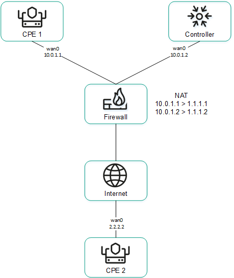
CPE 1 and the Controller are behind NAT and are connected to CPE 2
Providing IP addresses of WAN interfaces from an isolated network to the SD-WAN Controller
Some of the WAN interfaces of a CPE device may be on an isolated network without the possibility of establishing a TCP session with the SD-WAN Controller, but they can be used to build GENEVE tunnels. In this case, the Controller cannot obtain information about the IP addresses of isolated WAN interfaces and use it to build GENEVE tunnels between CPE devices.
In the figure below, CPE 1 and CPE 2 have two WAN interfaces each, but they can establish communication with the SD-WAN Controller only through their wan0 interfaces because the wan1 interfaces are on an isolated network (MPLS) that does not have access to the Controller. However, both wan1 interfaces can be used to build GENEVE tunnels.
Please note that if the communication channel used to interact with the SD-WAN Controller fails for one of the CPE devices, all other communication channels also cannot be used, even if they remain operational, because the Controller eliminates the device from the topology.
The IP addresses of the isolated WAN interfaces can be provided to the SD-WAN Controller through the orchestrator.
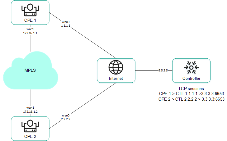
CPE 1 and CPE 2 are connected with each other through MPLS and with the SD-WAN Controller through the Internet.
You can configure the sending of the necessary information when creating or editing the SD-WAN interface.
Page topOverriding the IP address and port for connecting an interface to the SD-WAN controller
You can connect WAN interfaces to the SD-WAN Controller even if they use different types of communication channels, for example, the Internet vs a private MPLS network (see the figure below). In this case, you need to manually override IP addresses and ports for connecting to the Controller when creating or editing interfaces.
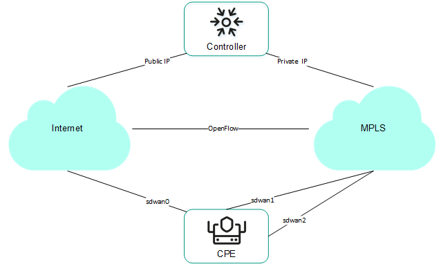
Connecting the CPE device to the Controller via two different communication channels
If your SD-WAN instance uses multiple Controller nodes, you must override IP addresses for all nodes. If the number of SD-WAN Controller nodes does not match the number of specified IP addresses, an error occurs and the values stay the same.
After overriding the IP address and port for connecting the interface to the SD-WAN Controller, you must restart the CPE device.
Page topCreating an SD-WAN interface
You can create an SD-WAN interface on an individual CPE device or on all devices that use the CPE template. SD-WAN interfaces are created on top of network interfaces, so you must first create a network interface.
To create an SD-WAN interface, use the following instructions:
- Creating an SD-WAN interface on an individual CPE device.
To create an SD-WAN interface on an individual CPE device:
- In the menu, go to the SD-WAN section.
By default, the CPE subsection is displayed with a table of CPE devices.
- Click the CPE device.
The settings area is displayed in the lower part of the page. You can expand the settings area to fill the entire page by clicking the expand button
. - Select the SD-WAN settings → Interfaces tab.
A table of SD-WAN interfaces is displayed.
- Click + SD-WAN interface.
- This opens a window; in that window, in the OpenFlow interface field, enter the number of the OpenFlow interface that must be created on the virtual switch of the CPE device.
- In the Interface (alias) field, enter the alias of the network interface to which you want to bind the OpenFlow interface.
- In the Maximum rate field, enter the maximum speed of the SD-WAN interface in Mbps. Range of values: 1 to 100,000. The default setting is
1,000. - Specify the host whose availability determines the availability of the SD-WAN interface:
- In the IP for tracking field, enter the IP address of the host.
- Click + Add.
You can specify multiple hosts.
- In the Reliability field, enter the number of hosts that must remain available for the SD-WAN interface to be considered available. The default setting is
1.Make sure that the number of hosts does not exceed the number of IP addresses in the IP for tracking field. Otherwise, the SD-WAN interface will always be considered unavailable.
- In the Interval field, enter the SD-WAN interface testing interval in seconds. Range of values: 1 to 600. The default setting is
2. - In the Count field, enter the number of availability checks for each of the specified hosts as part of a single SD-WAN interface test. Range of values: 1 to 600. The default setting is
2. - In the Timeout field, enter the time in milliseconds for the SD-WAN interface to wait for an echo response from the hosts after sending an echo request. Range of values: 1 to 100,000. The default setting is
2000. - In the Down field, enter the interval in seconds for testing the SD-WAN interface if it becomes unavailable. Range of values: 1 to 600. The default setting is
3. - In the Up field, enter the interval in seconds for testing the SD-WAN interface if it becomes available again. Range of values: 1 to 600. The default setting is
2. - In the Speed monitoring drop-down list, select whether to check the speed limit of the SD-WAN interface imposed by the mobile operator:
- Yes
- No (selected by default)
- If necessary, configure traffic queues on the SD-WAN interface:
- Select the QoS tab.
A table of traffic queues is displayed.
- In the Remap ToS column, select the Type of Service value of external headers of traffic packets for each queue. You cannot select these values when configuring traffic queues for the LAN interface.
- In the Minimum Speed, % column, specify the minimum traffic bandwidth for the queue as a percentage of the maximum speed of the SD-WAN interface. The sum total in a column may not exceed 100.
- In the Maximum Speed, % column, specify the maximum traffic bandwidth for the queue as a percentage of the maximum speed of the SD-WAN interface. This setting is used to prevent traffic of high-priority queues from indefinitely preempting traffic of low-priority queues.
The maximum speed of the interface is specified when configuring the connection of the CPE device to the SD-WAN network on the General settings tab in the Maximum rate field.
- Select the QoS tab.
- If necessary, configure the sending of interface information to the SD-WAN Controller:
- Select the NAT and Disjoint WAN underlay tab.
- In the State drop-down list, select one of the following values:
- Disabled if the SD-WAN Controller does not need to receive information about the interface.
- NAT/PAT if the interface is behind NAT or PAT and needs to be assigned a public IP address and UDP port number, which must be sent to the SD-WAN Controller.
- Disjoint WAN Underlay if the interface is on an isolated network and its IP address must be sent to the SD-WAN Controller.
- If in the State drop-down list, you selected NAT/PAT, follow these steps:
- In the Real IP Address field, enter the public IP address (IPv4) of the interface.
- In the Real GENEVE UDP Port field, enter the UDP port number of the interface. Range of values: 1 to 65,353.
- If in the State drop-down list, you selectedDisjoint WAN Underlay, in the IP address field, enter the IP address (IPv4) of the interface. You must enter the IP address specified when creating the network interface over which the SD-WAN interface is created.
- If necessary, override the IP address and port for connecting the interface to the SD-WAN Controller:
- Select the Controllers tab.
- Select the Rewrite controllers IP/Port check box. This check box is cleared by default.
- In the Controllers QTY drop-down list, select the number of Controller nodes in your SD-WAN instance.
You must override the IP address for connecting the interface to each node of the SD-WAN Controller. Otherwise, an error occurs and the settings remain unchanged.
- In the Port field, enter the starting port number for connecting the interface to the SD-WAN Controller. The number of fields corresponds to the value that you selected in the Controllers QTY drop-down list. Range of values: 1 to 65,535. The default setting is
6653.The starting port is used to configure the ports for connecting to the SD-WAN Controller. The number of configured ports depends on the number of WAN interfaces of the CPE device. For example, if you enter
6653as the starting port number and the device has four WAN interfaces, port numbers 6654, 6655, and 6656 are derived from that port. - In the IP address field, enter the IP address (IPv4) for connecting the interface to the SD-WAN Controller. The number of fields corresponds to the value that you selected in the Controllers QTY drop-down list.
After overriding the IP address and port for connecting the interface to the SD-WAN Controller, you must restart the CPE device.
- Click Create.
The SD-WAN interface is created and displayed in the table.
- In the upper part of the settings area, click Save to save the configuration of the CPE device.
- In the menu, go to the SD-WAN section.
- Creating an SD-WAN interface on all devices that use the CPE template.
To create an SD-WAN interface on all devices that use the CPE template:
- In the menu, go to the SD-WAN → CPE templates subsection.
A table of CPE templates is displayed.
- Click the CPE template.
The settings area is displayed in the lower part of the page. You can expand the settings area to fill the entire page by clicking the expand button
. - Select the SD-WAN settings → Interfaces tab.
A table of SD-WAN interfaces is displayed.
- Click + SD-WAN interface.
- This opens a window; in that window, in the OpenFlow interface field, enter the number of the OpenFlow interface that must be created on the virtual switch of the CPE device.
- In the Interface (alias) field, enter the alias of the network interface to which you want to bind the OpenFlow interface.
- In the Maximum rate field, enter the maximum speed of the SD-WAN interface in Mbps. Range of values: 1 to 100,000. The default setting is
1,000. - Specify the host whose availability determines the availability of the SD-WAN interface:
- In the IP for tracking field, enter the IP address of the host.
- Click + Add.
You can specify multiple hosts.
- In the Reliability field, enter the number of hosts that must remain available for the SD-WAN interface to be considered available. The default setting is
1.Make sure that the number of hosts does not exceed the number of IP addresses in the IP for tracking field. Otherwise, the SD-WAN interface will always be considered unavailable.
- In the Interval field, enter the SD-WAN interface testing interval in seconds. Range of values: 1 to 600. The default setting is
2. - In the Count field, enter the number of availability checks for each of the specified hosts as part of a single SD-WAN interface test. Range of values: 1 to 600. The default setting is
2. - In the Timeout field, enter the time in milliseconds for the SD-WAN interface to wait for an echo response from the hosts after sending an echo request. Range of values: 1 to 100,000. The default setting is
2000. - In the Down field, enter the interval in seconds for testing the SD-WAN interface if it becomes unavailable. Range of values: 1 to 600. The default setting is
3. - In the Up field, enter the interval in seconds for testing the SD-WAN interface if it becomes available again. Range of values: 1 to 600. The default setting is
2. - In the Speed monitoring drop-down list, select whether to check the speed limit of the SD-WAN interface imposed by the mobile operator:
- Yes
- No (selected by default)
- If necessary, configure traffic queues on the SD-WAN interface:
- Select the QoS tab.
A table of traffic queues is displayed.
- In the Remap ToS column, select the Type of Service value of external headers of traffic packets for each queue. You cannot select these values when configuring traffic queues for the LAN interface.
- In the Minimum Speed, % column, specify the minimum traffic bandwidth for the queue as a percentage of the maximum speed of the SD-WAN interface. The sum total in a column may not exceed 100.
- In the Maximum Speed, % column, specify the maximum traffic bandwidth for the queue as a percentage of the maximum speed of the SD-WAN interface. This setting is used to prevent traffic of high-priority queues from indefinitely preempting traffic of low-priority queues.
The maximum speed of the interface is specified when configuring the connection of the CPE device to the SD-WAN network on the General settings tab in the Maximum rate field.
- Select the QoS tab.
- If necessary, configure the sending of interface information to the SD-WAN Controller:
- Select the NAT and Disjoint WAN underlay tab.
- In the State drop-down list, select one of the following values:
- Disabled if the SD-WAN Controller does not need to receive information about the interface.
- NAT/PAT if the interface is behind NAT or PAT and needs to be assigned a public IP address and UDP port number, which must be sent to the SD-WAN Controller.
- Disjoint WAN Underlay if the interface is on an isolated network and its IP address must be sent to the SD-WAN Controller.
- If in the State drop-down list, you selected NAT/PAT, follow these steps:
- In the Real IP Address field, enter the public IP address (IPv4) of the interface.
- In the Real GENEVE UDP Port field, enter the UDP port number of the interface. Range of values: 1 to 65,353.
- If in the State drop-down list, you selectedDisjoint WAN Underlay, in the IP address field, enter the IP address (IPv4) of the interface. You must enter the IP address specified when creating the network interface over which the SD-WAN interface is created.
- If necessary, override the IP address and port for connecting the interface to the SD-WAN Controller:
- Select the Controllers tab.
- Select the Rewrite controllers IP/Port check box. This check box is cleared by default.
- In the Controllers QTY drop-down list, select the number of Controller nodes in your SD-WAN instance.
You must override the IP address for connecting the interface to each node of the SD-WAN Controller. Otherwise, an error occurs and the settings remain unchanged.
- In the Port field, enter the starting port number for connecting the interface to the SD-WAN Controller. The number of fields corresponds to the value that you selected in the Controllers QTY drop-down list. Range of values: 1 to 65,535. The default setting is
6653.The starting port is used to configure the ports for connecting to the SD-WAN Controller. The number of configured ports depends on the number of WAN interfaces of the CPE device. For example, if you enter
6653as the starting port number and the device has four WAN interfaces, port numbers 6654, 6655, and 6656 are derived from that port. - In the IP address field, enter the IP address (IPv4) for connecting the interface to the SD-WAN Controller. The number of fields corresponds to the value that you selected in the Controllers QTY drop-down list.
After overriding the IP address and port for connecting the interface to the SD-WAN Controller, you must restart the CPE device.
- Click Create.
The SD-WAN interface is created and displayed in the table.
- In the upper part of the settings area, click Save to save the configuration of the CPE template.
- In the menu, go to the SD-WAN → CPE templates subsection.
Editing an SD-WAN interface
You can edit an SD-WAN interface on an individual CPE device or on all devices that use the CPE template. For a description of the settings, see the instructions for creating an SD-WAN interface.
To edit an SD-WAN interface on an individual CPE device:
- In the menu, go to the SD-WAN section.
By default, the CPE subsection is displayed with a table of CPE devices.
- Click the CPE device.
The settings area is displayed in the lower part of the page. You can expand the settings area to fill the entire page by clicking the expand button
. - Select the SD-WAN settings → Interfaces tab.
A table of SD-WAN interfaces is displayed.
- Select the Override check box next to the SD-WAN interface to ignore the applied CPE template and be able to edit the interface settings. This check box is cleared by default.
- Click Edit.
- This opens a window; in that window, edit the settings of the SD-WAN interface that you want to change:
- Click Save.
- In the upper part of the settings area, click Save to save the configuration of the CPE device.
To edit an SD-WAN interface on all devices that use the CPE template:
- In the menu, go to the SD-WAN → CPE templates subsection.
A table of CPE templates is displayed.
- Click the CPE template.
The settings area is displayed in the lower part of the page. You can expand the settings area to fill the entire page by clicking the expand button
. - Select the SD-WAN settings → Interfaces tab.
A table of SD-WAN interfaces is displayed.
- Click Edit next to the SD-WAN interface.
- This opens a window; in that window, edit the settings of the SD-WAN interface that you want to change:
- Click Save.
- In the upper part of the settings area, click Save to save the configuration of the CPE template.
Disabling an SD-WAN interface
You can disable an SD-WAN interface on an individual CPE device or on all devices that use the CPE template.
To disable an SD-WAN interface on an individual CPE device:
- In the menu, go to the SD-WAN section.
By default, the CPE subsection is displayed with a table of CPE devices.
- Click the CPE device.
The settings area is displayed in the lower part of the page. You can expand the settings area to fill the entire page by clicking the expand button
. - Select the SD-WAN settings → Interfaces tab.
A table of SD-WAN interfaces is displayed.
- Select the Override check box next to the SD-WAN interface to ignore the applied CPE template and be able to disable the interface. This check box is cleared by default.
- Click Disable.
- In the upper part of the settings area, click Save to save the configuration of the CPE device.
To disable an SD-WAN interface on all devices that use the CPE template:
- In the menu, go to the SD-WAN → CPE templates subsection.
A table of CPE templates is displayed.
- Click the CPE template.
The settings area is displayed in the lower part of the page. You can expand the settings area to fill the entire page by clicking the expand button
. - Select the SD-WAN settings → Interfaces tab.
A table of SD-WAN interfaces is displayed.
- Click Disable next to the SD-WAN interface.
- In the upper part of the settings area, click Save to save the configuration of the CPE template.
Deleting an SD-WAN interface
You can delete an SD-WAN interface on an individual CPE device or on all devices that use the CPE template. On an individual CPE device, you can delete only those SD-WAN interfaces that were created locally and not the ones that were inherited from the template. Deleted SD-WAN interfaces cannot be restored.
To delete a network interface on an individual CPE device:
- In the menu, go to the SD-WAN section.
By default, the CPE subsection is displayed with a table of CPE devices.
- Click the CPE device.
The settings area is displayed in the lower part of the page. You can expand the settings area to fill the entire page by clicking the expand button
. - Select the SD-WAN settings → Interfaces tab.
A table of SD-WAN interfaces is displayed.
- Click Delete next to the SD-WAN interface.
- In the confirmation window, click Delete.
The SD-WAN interface is deleted and is no longer displayed in the table.
To delete an SD-WAN interface on all devices that use the CPE template:
- In the menu, go to the SD-WAN → CPE templates subsection.
A table of CPE templates is displayed.
- Click the CPE template.
The settings area is displayed in the lower part of the page. You can expand the settings area to fill the entire page by clicking the expand button
. - Select the SD-WAN settings → Interfaces tab.
A table of SD-WAN interfaces is displayed.
- Click Delete next to the SD-WAN interface.
- In the confirmation window, click Delete.
The SD-WAN interface is deleted and is no longer displayed in the table.
Page topOpenFlow interfaces
OpenFlow interfaces are interfaces of the overlay SDN that are automatically created at the same time as the SD-WAN interfaces. The SD-WAN Controller uses OpenFlow interfaces to control network traffic. Service interfaces and UNIs are created on top of the OpenFlow interfaces.
You can group OpenFlow interfaces and use the groups when creating M2M and P2M transport services. When you add a group of OpenFlow interfaces to a transport service, a service interface is automatically created on top of each interface in the group, which in turn is used by the transport service.
Using groups of OpenFlow interfaces eliminates the need to manually create service interfaces and add them to transport services.
Creating a group of OpenFlow interfaces
To create a group of OpenFlow interfaces:
- In the menu, go to the Infrastructure section.
The SD-WAN infrastructure management page is displayed. By default, the Network resources tab is selected, which displays the table of SD-WAN Controllers.
- Click Management next to the SD-WAN Controller and in the drop-down list, select Configuration menu.
This opens the SD-WAN Controller configuration menu. By default, you are taken to the Controller nodes section, which displays a table of Controller nodes.
- Go to the OpenFlow groups section.
A table of groups of OpenFlow interfaces is displayed.
- In the upper part of the page, click + OpenFlow group.
- This opens a window; in that window, in the Name field, enter the name of the OpenFlow interface group.
- In the Switch and Port drop-down lists, select the CPE device and OpenFlow interface that you want to add to the group.
- Click Create.
The group of OpenFlow interfaces is created and displayed in the table.
Page topEditing a group of OpenFlow interfaces
To edit a group of OpenFlow interfaces:
- In the menu, go to the Infrastructure section.
The SD-WAN infrastructure management page is displayed. By default, the Network resources tab is selected, which displays the table of SD-WAN Controllers.
- Click Management next to the SD-WAN Controller and in the drop-down list, select Configuration menu.
This opens the SD-WAN Controller configuration menu. By default, you are taken to the Controller nodes section, which displays a table of Controller nodes.
- Go to the OpenFlow groups section.
A table of groups of OpenFlow interfaces is displayed.
- Click Management next to the group of OpenFlow interfaces and in the drop-down list, select Edit.
- This opens a window; in that window, edit the settings that you want to change. For a description of the settings, see the instructions for creating a group of OpenFlow interfaces.
- Click Save.
Deleting a group of OpenFlow interfaces
Deleted groups of OpenFlow interfaces cannot be restored.
To delete a group of OpenFlow interfaces:
- In the menu, go to the Infrastructure section.
The SD-WAN infrastructure management page is displayed. By default, the Network resources tab is selected, which displays the table of SD-WAN Controllers.
- Click Management next to the SD-WAN Controller and in the drop-down list, select Configuration menu.
This opens the SD-WAN Controller configuration menu. By default, you are taken to the Controller nodes section, which displays a table of Controller nodes.
- Go to the OpenFlow groups section.
A table of groups of OpenFlow interfaces is displayed.
- Click Management next to the group of OpenFlow interfaces and in the drop-down list, select Delete.
- In the confirmation window, click Delete.
The group of OpenFlow interfaces is deleted and is no longer displayed in the table.
Page topService interfaces and UNIs
Service interfaces and UNIs are interfaces for connecting devices to transport and network services. These interfaces can be created on top of any OpenFlow interfaces except those corresponding to the WAN interfaces of the SD-WAN.
In turn, on top of service interfaces, you can create ACL interfaces that filter traffic between transport services based on specified constraints.
You can create all necessary UNIs in one UNI template, and then apply it to a CPE device when creating and registering that device. In this case, all UNIs from the template are automatically created on the CPE device.
The difference between UNI (user network interfaces) and service interfaces is that UNIs are used when creating network services, and service interfaces are used when creating transport services. In addition, service interfaces cannot be added to the graphical designer tool that is used to build the network service topology, or assigned to tenants.
Note that when you create a UNI, a corresponding service interface is automatically created for it, but for service interfaces, UNIs are not created.
Creating a service interface
To create a service interface:
- In the menu, go to the Infrastructure section.
The SD-WAN infrastructure management page is displayed. By default, the Network resources tab is selected, which displays the table of SD-WAN Controllers.
- Click Management next to the SD-WAN Controller and in the drop-down list, select Configuration menu.
This opens the SD-WAN Controller configuration menu. By default, you are taken to the Controller nodes section, which displays a table of Controller nodes.
- Go to the Service interfaces section.
A table of service and ACL interfaces is displayed.
- In the upper part of the page, in the Switch and Port drop-down lists, select a CPE device and an OpenFlow interface.
- Click Create service interface.
- This opens a window; in that window, in the Type drop-down list, select the type of encapsulation on the service interface:
- Access (selected by default).
- VLAN
- Q-in-Q.
- ACL — Used for creating an ACL interface.
- If in the Type drop-down list, you selected VLAN, in the VLAN ID field, enter the outer VLAN tag. Range of values: 1 to 4,094.
- If in the Type drop-down list, you selected Q-in-Q, follow these steps:
- In the VLAN ID field, enter the outer VLAN tag. Range of values: 1 to 4,094.
- In the Inner VLAN ID field, enter the inner VLAN tag. Range of values: 1 to 4,094.
- If necessary, enter a brief description of the service interface in the Description field.
- Click Create.
The service interface is created and displayed in the table.
Page topCreating an ACL interface
The ACL interface is created on top of the service interface, it filters traffic transmitted between transport services. Before creating an ACL interface, you must complete the following steps:
To create an ACL interface:
- In the menu, go to the Infrastructure section.
The SD-WAN infrastructure management page is displayed. By default, the Network resources tab is selected, which displays the table of SD-WAN Controllers.
- Click Management next to the SD-WAN Controller and in the drop-down list, select Configuration menu.
This opens the SD-WAN Controller configuration menu. By default, you are taken to the Controller nodes section, which displays a table of Controller nodes.
- Go to the Service interfaces section.
A table of service and ACL interfaces is displayed.
- In the upper part of the page, in the Switch and Port drop-down lists, select a CPE device and an OpenFlow interface.
- Click + Create service interface.
- This opens a window; in that window, in the Type drop-down list, select ACL.
- In the Service interface drop-down list, select the service interface on top of which you want to create the ACL interface.
- In the Traffic fliter drop-down list, select the previously created traffic filter for the ACL interface. You can use the same traffic filter for multiple ACL interfaces.
- In the Sequence drop-down list, select the sequential number of the ACL interface. Traffic is directed first to the ACL interface with the lowest number. If the filter used on an ACL interface drops traffic, it is forwarded to the second ACL interface, and so on.
Range of values: 1 to 4. You cannot create two ACL interfaces with the same match order value on top of one service interface.
- If necessary, enter a brief description of the ACL interface in the Description field.
- Click Create.
The ACL interface is created and displayed in the table.
Viewing the usage of a service interface and an ACL interface
You can view which solution components are using a service interface or an ACL interface.
To view the usage of a service interface or ACL interface:
- In the menu, go to the Infrastructure section.
The SD-WAN infrastructure management page is displayed. By default, the Network resources tab is selected, which displays the table of SD-WAN Controllers.
- Click Management next to the SD-WAN Controller and in the drop-down list, select Configuration menu.
This opens the SD-WAN Controller configuration menu. By default, you are taken to the Controller nodes section, which displays a table of Controller nodes.
- Go to the Service interfaces section.
A table of service and ACL interfaces is displayed.
- Click Management next to the interface and in the drop-down list, select Show usage.
This opens a window displaying a table of all solution components that use the interface.
Page topDeleting a service interface and an ACL interface
You cannot delete a service interface or ACL interface that is being used by a solution component, such as a transport service. Deleted interfaces cannot be restored.
To delete a service interface or an ACL interface:
- In the menu, go to the Infrastructure section.
The SD-WAN infrastructure management page is displayed. By default, the Network resources tab is selected, which displays the table of SD-WAN Controllers.
- Click Management next to the SD-WAN Controller and in the drop-down list, select Configuration menu.
This opens the SD-WAN Controller configuration menu. By default, you are taken to the Controller nodes section, which displays a table of Controller nodes.
- Go to the Service interfaces section.
A table of service and ACL interfaces is displayed.
- Click Management next to the interface and in the drop-down list, select Delete.
- In the confirmation window, click Delete.
The interface is deleted and is no longer displayed in the table.
Page topCreating a UNI template
A UNI template can be used for centralized creation of UNIs on CPE devices. After the template is created, the necessary UNIs are created in it. The template is then applied to a device when that device is created or registered. All UNIs created in the template are automatically created on the device.
To create a UNI template:
- In the menu, go to the SD-WAN section.
By default, the CPE subsection is displayed with a table of CPE devices.
- In the upper part of the page, click + UNI template.
- This opens a window; in that window, enter the name of the template and click Create.
The UNI templates subsection is displayed with a table of UNI templates. The template is created and displayed in the table.
You must create a UNI in the UNI template.
Page topCreating a UNI in a template
After creating the template, you must create the necessary UNIs in it. When you apply a template to a CPE device, all UNIs created in the template are automatically created on that device. Before you can create a UNI in a template, you must create a UNI template.
To create a UNI in a template:
- In the menu, go to the SD-WAN → UNI templates subsection.
A table of UNI templates is displayed.
- Click the UNI template.
The settings area is displayed in the lower part of the page. You can expand the settings area to fill the entire page by clicking the expand button
. - Select the UNI tab.
A table of UNIs is displayed.
- Click + UNI.
- This opens a window; in that window, in the Name field, enter the name of the UNI.
- In the OpenFlow interface field, enter the number of the OpenFlow interface on top of which you want to create a UNI.
- In the OpenFlow interface drop-down list, select the UNI encapsulation type:
- Access (selected by default).
- VLAN
- Q-in-Q
- If in the Encapsulation drop-down list, you selected VLAN, in the VLAN ID field, enter the outer VLAN tag. Range of values: 1 to 4094.
- If in the Encapsulation drop-down list, you selected Q-in-Q, follow these steps:
- In the VLAN ID field, enter the outer VLAN tag. Range of values: 1 to 4,094.
- In the Inner VLAN ID field, enter the inner VLAN tag. Range of values: 1 to 4,094.
- Click Create.
The UNI is created in the template and displayed in the table.
- In the upper part of the settings area, click Save to save the configuration of the UNI template.
Editing a UNI in a template
To edit a UNI in a template:
- In the menu, go to the SD-WAN → UNI templates subsection.
A table of UNI templates is displayed.
- Click the UNI template.
The settings area is displayed in the lower part of the page. You can expand the settings area to fill the entire page by clicking the expand button
. - Select the UNI tab.
A table of UNIs is displayed.
- Click Edit next to the UNI.
- This opens a window; in that window, edit the settings that you want to change. For a description of the settings, see the instructions for creating a UNI in a template.
- Click Save.
- In the upper part of the settings area, click Save to save the configuration of the UNI template.
Deleting a UNI in a template
UNIs that are deleted in the template cannot be restored.
To delete a UNI in a template:
- In the menu, go to the SD-WAN → UNI templates subsection.
A table of UNI templates is displayed.
- Click the UNI template.
The settings area is displayed in the lower part of the page. You can expand the settings area to fill the entire page by clicking the expand button
. - Select the UNI tab.
A table of UNIs is displayed.
- Click Delete next to the UNI.
The UNI is deleted and is no longer displayed in the table.
- In the upper part of the settings area, click Save to save the configuration of the UNI template.
Deleting a UNI template
Deleted UNI templates cannot be restored.
To delete a UNI template:
- In the menu, go to the SD-WAN → UNI templates subsection.
A table of UNI templates is displayed.
- Click the UNI template.
The settings area is displayed in the lower part of the page. You can expand the settings area to fill the entire page by clicking the expand button
. - In the upper part of the settings area, under Actions click Delete.
- In the confirmation window, click Delete.
The UNI template is deleted and is no longer displayed in the table.
Page topCreating a UNI
You can create a UNI on an individual CPE device. Before creating an UNI, you must complete the following steps:
- Activate the CPE device.
- Create a QoS rule.
To create a UNI on a CPE device:
- In the menu, go to the SD-WAN section.
By default, the CPE subsection is displayed with a table of CPE devices.
- Click the CPE device.
The settings area is displayed in the lower part of the page. You can expand the settings area to fill the entire page by clicking the expand button
. - Select the UNI tab.
A table of UNIs is displayed.
- Click + UNI.
- This opens a window; in that window, in the Name field, enter the name of the UNI.
- In the Port drop-down list, select the OpenFlow interface on top of which you want to create a UNI.
- In the Encapsulation drop-down list, select the UNI encapsulation type:
- Access (selected by default)
- VLAN
- Q-in-Q
- If in the Encapsulation drop-down list, you selected VLAN, in the VLAN ID field, enter the outer VLAN tag. Range of values: 1 to 4094.
- If in the Encapsulation drop-down list, you selected Q-in-Q, follow these steps:
- In the VLAN ID field, enter the outer VLAN tag. Range of values: 1 to 4,094.
- In the Inner VLAN ID field, enter the inner VLAN tag. Range of values: 1 to 4,094.
- In the QoS drop-down list, select the previously created QoS rule for the UNI.
- Click Create.
The UNI is created and displayed in the table.
- In the upper part of the settings area, click Save to save the configuration of the CPE device.
Editing a UNI
You can edit a UNI on an individual CPE device.
To edit a UNI:
- In the menu, go to the SD-WAN section.
By default, the CPE subsection is displayed with a table of CPE devices.
- Click the CPE device.
The settings area is displayed in the lower part of the page. You can expand the settings area to fill the entire page by clicking the expand button
. - Select the UNI tab.
A table of UNIs is displayed.
- Click Edit next to the UNI.
- This opens a window; in that window, edit the settings that you want to change. For a description of the settings, see the instructions for creating a UNI.
- Click Save.
- In the upper part of the settings area, click Save to save the configuration of the CPE device.
Deleting a UNI
You can delete a UNI on an individual CPE device. Deleted UNIs cannot be restored.
To delete a UNI:
- In the menu, go to the SD-WAN section.
By default, the CPE subsection is displayed with a table of CPE devices.
- Click the CPE device.
The settings area is displayed in the lower part of the page. You can expand the settings area to fill the entire page by clicking the expand button
. - Select the UNI tab.
A table of UNIs is displayed.
- Click Delete next to the UNI.
The UNI is deleted and is no longer displayed in the table.
- In the upper part of the settings area, click Save to save the configuration of the CPE device.
Filtering routes
Route filtering lets you manage the advertisement of network routes based on criteria that you can specify. This functionality is necessary for optimal performance and security of the network, and for preventing routing loops.
You can use route filtering to allow or prohibit the advertising of specific routes between CPE devices and third-party network devices, as well as between individual autonomous systems. For route filtering, Kaspersky SD-WAN uses access control lists (ACLs), prefix lists, and route maps.
Access control lists
An access control list is a set of rules for filtering routing information on a CPE device based on IP addresses and prefixes of the networks to which the routes belong.
Rules in an access control list can allow or deny the advertising of routes that belong to a specific network. Each rule is numbered. The CPE compares the information about the network to which the route belongs to the conditions of the rules in the access control list that is being used, starting with the rule with the lowest number.
Prefix lists
A prefix list is an extended version of an access control list. The distinction of the prefix list is that it can contain rules that filter routes based on IP addresses and ranges of network prefixes (rather than individual prefixes).
Route maps
While the access control list and prefix list are always applied to advertised routes, a route map is applied to routes only when specified conditions are met, and it can change the attributes of routes.
If none of the rules in the access control list, prefix list, or route map can be applied to a route, that route is discarded.
Creating an access-control list (ACL)
You can create an access control list on an individual CPE device or on all devices that use the CPE template. To create an access control list, use the following instructions:
- Creating an access control list on an individual CPE device.
To create an access control list on an individual CPE device:
- In the menu, go to the SD-WAN section.
By default, the CPE subsection is displayed with a table of CPE devices.
- Click the CPE device.
The settings area is displayed in the lower part of the page. You can expand the settings area to fill the entire page by clicking the expand button
. - Select the Routing Filters tab.
The Access control lists tab, which is selected by default, displays the table of access control lists.
- Select the Override check box to ignore the applied CPE template and make the settings in the selected tab editable. This check box is cleared by default.
- Click + Access control list.
- This opens a window; in that window, in the Name field, enter the name of the access control list. Maximum length: 50 characters. Do not use spaces in this field.
- Click + Add rule to add a rule to the access control list. You can add multiple rules.
- In the Sequence field, enter the sequential number of the rule. The rule with the lowest number is processed first. Range of values: 1 to 4,294,967,295.
- In the Network drop-down list, select the type of the rule:
- Any network for a rule that allows or denies advertising of any networks.
- IP/mask for a rule that allows or denies the advertising of a specific network. This is the default setting.
- If in the Network drop-down list, you selected IP/mask, in the field that is displayed, enter the IP address and the network prefix.
- In the Action drop-down list, select the action that the rule must apply to routes:
- Permitto allow route advertising. This is the default setting.
- Deny to deny route advertising.
- Click Create.
The access control list is created and displayed in the table.
- In the upper part of the settings area, click Save to save the configuration of the CPE device.
- In the menu, go to the SD-WAN section.
- Creating an access control list on all devices that use the CPE template.
To create an access control list on all devices that use the CPE template:
- In the menu, go to the SD-WAN → CPE templates subsection.
A table of CPE templates is displayed.
- Click the CPE template.
The settings area is displayed in the lower part of the page. You can expand the settings area to fill the entire page by clicking the expand button
. - Select the Routing Filters tab.
The Access control lists tab, which is selected by default, displays the table of access control lists.
- Click + Access control list.
- This opens a window; in that window, in the Name field, enter the name of the access control list. Maximum length: 50 characters. Do not use spaces in this field.
- Click + Add rule to add a rule to the access control list. You can add multiple rules.
- In the Sequence field, enter the sequential number of the rule. The rule with the lowest number is processed first. Range of values: 1 to 4,294,967,295.
- In the Network drop-down list, select the type of the rule:
- Any network for a rule that allows or denies advertising of any networks.
- IP/mask for a rule that allows or denies the advertising of a specific network. This is the default setting.
- If in the Network drop-down list, you selected IP/mask, in the field that is displayed, enter the IP address and the network prefix.
- In the Action drop-down list, select the action that the rule must apply to routes:
- Permitto allow route advertising. This is the default setting.
- Deny to deny route advertising.
- Click Create.
The access control list is created and displayed in the table.
- In the upper part of the settings area, click Save to save the configuration of the CPE template.
- In the menu, go to the SD-WAN → CPE templates subsection.
Editing an access control list
You can edit an access control list on an individual CPE device or on all devices that use the CPE template. For a description of the settings, see the instructions for creating an access control list.
To edit an access control list on an individual CPE device:
- In the menu, go to the SD-WAN section.
By default, the CPE subsection is displayed with a table of CPE devices.
- Click the CPE device.
The settings area is displayed in the lower part of the page. You can expand the settings area to fill the entire page by clicking the expand button
. - Select the Routing Filters tab.
The Access control lists tab, which is selected by default, displays the table of access control lists.
- Select the Override check box to ignore the applied CPE template and make the settings in the selected tab editable. This check box is cleared by default.
- Click Edit next to the access control list.
- This opens a window; in that window, edit the settings that you want to change.
- Click Save.
- In the upper part of the settings area, click Save to save the configuration of the CPE device.
To edit an access control list on all devices that use the CPE template:
- In the menu, go to the SD-WAN → CPE templates subsection.
A table of CPE templates is displayed.
- Click the CPE template.
The settings area is displayed in the lower part of the page. You can expand the settings area to fill the entire page by clicking the expand button
. - Select the Routing Filters tab.
The Access control lists tab, which is selected by default, displays the table of access control lists.
- Click Edit next to the access control list.
- This opens a window; in that window, edit the settings that you want to change.
- Click Save.
- In the upper part of the settings area, click Save to save the configuration of the CPE template.
Deleting an access control list
You can delete an access control list on an individual CPE device or on all devices that use the CPE template. Deleted access control lists cannot be restored.
To delete an access control list on an individual CPE device:
- In the menu, go to the SD-WAN section.
By default, the CPE subsection is displayed with a table of CPE devices.
- Click the CPE device.
The settings area is displayed in the lower part of the page. You can expand the settings area to fill the entire page by clicking the expand button
. - Select the Routing Filters tab.
The Access control lists tab, which is selected by default, displays the table of access control lists.
- Select the Override check box to ignore the applied CPE template and make the settings in the selected tab editable. This check box is cleared by default.
- Click Delete next to the access control list.
- In the confirmation window, click Delete.
The access control list is deleted and is no longer displayed in the table.
- In the upper part of the settings area, click Save to save the configuration of the CPE device.
To delete an access control list on all devices that use the CPE template:
- In the menu, go to the SD-WAN → CPE templates subsection.
A table of CPE templates is displayed.
- Click the CPE template.
The settings area is displayed in the lower part of the page. You can expand the settings area to fill the entire page by clicking the expand button
. - Select the Routing Filters tab.
The Access control lists tab, which is selected by default, displays the table of access control lists.
- Click Delete next to the access control list.
- In the confirmation window, click Delete.
The access control list is deleted and is no longer displayed in the table.
- In the upper part of the settings area, click Save to save the configuration of the CPE template.
Creating a prefix list
You can create a prefix list on an individual CPE device or on all devices that use the CPE template. To create a prefix list, use the following instructions:
- Creating a prefix list on an individual CPE device.
To create a prefix list on an individual CPE device:
- In the menu, go to the SD-WAN section.
By default, the CPE subsection is displayed with a table of CPE devices.
- Click the CPE device.
The settings area is displayed in the lower part of the page. You can expand the settings area to fill the entire page by clicking the expand button
. - Select the Routing Filters → Prefix lists tab.
A table of prefix lists is displayed.
- Select the Override check box to ignore the applied CPE template and make the settings in the selected tab editable. This check box is cleared by default.
- Click + Prefix list.
- This opens a window; in that window, in the Name field, enter the name of the prefix list. Maximum length: 50 characters. Do not use spaces in this field.
- Click + Add rule to add a rule to the prefix list. You can add multiple rules.
- In the Sequence field, enter the sequential number of the rule. The rule with the lowest number is processed first. Range of values: 1 to 4,294,967,295.
- In the Network drop-down list, select the type of the rule:
- Any network for a rule that allows or denies advertising of any networks.
- IP/mask for a rule that allows or denies the advertising of a specific network. This is the default setting.
- If in the Network drop-down list, you selected IP/mask, in the field that is displayed, enter the IP address and the network prefix.
- In the Action drop-down list, select the action that the rule must apply to routes:
- Permit to allow route advertising. This is the default setting.
- Deny to deny route advertising.
- In the Greater or equal and Less or equal fields, enter the starting and ending values for the range of prefixes. Range of values in each field: 0 to 32.
- Click Create.
The prefix list is created and displayed in the table.
- In the upper part of the settings area, click Save to save the configuration of the CPE device.
- In the menu, go to the SD-WAN section.
- Creating a prefix list on all devices that use the CPE template.
To create a prefix list on all devices that use the CPE template:
- In the menu, go to the SD-WAN → CPE templates subsection.
A table of CPE templates is displayed.
- Click the CPE template.
The settings area is displayed in the lower part of the page. You can expand the settings area to fill the entire page by clicking the expand button
. - Select the Routing Filters → Prefix lists tab.
A table of prefix lists is displayed.
- Click + Prefix list.
- This opens a window; in that window, in the Name field, enter the name of the prefix list. Maximum length: 50 characters. Do not use spaces in this field.
- Click + Add rule to add a rule to the prefix list. You can add multiple rules.
- In the Sequence field, enter the sequential number of the rule. The rule with the lowest number is processed first. Range of values: 1 to 4,294,967,295.
- In the Network drop-down list, select the type of the rule:
- Any network for a rule that allows or denies advertising of any networks.
- IP/mask for a rule that allows or denies the advertising of a specific network. This is the default setting.
- If in the Network drop-down list, you selected IP/mask, in the field that is displayed, enter the IP address and the network prefix.
- In the Action drop-down list, select the action that the rule must apply to routes:
- Permit to allow route advertising. This is the default setting.
- Deny to deny route advertising.
- In the Greater or equal and Less or equal fields, enter the starting and ending values for the range of prefixes. Range of values in each field: 0 to 32.
- Click Create.
The prefix list is created and displayed in the table.
- In the upper part of the settings area, click Save to save the configuration of the CPE template.
- In the menu, go to the SD-WAN → CPE templates subsection.
Editing a prefix list
You can edit a prefix list on an individual CPE device or on all devices that use the CPE template. For a description of the settings, see the instructions for creating a prefix list.
To edit a prefix list on an individual CPE device:
- In the menu, go to the SD-WAN section.
By default, the CPE subsection is displayed with a table of CPE devices.
- Click the CPE device.
The settings area is displayed in the lower part of the page. You can expand the settings area to fill the entire page by clicking the expand button
. - Select the Routing Filters → Prefix lists tab.
A table of prefix lists is displayed.
- Select the Override check box to ignore the applied CPE template and make the settings in the selected tab editable. This check box is cleared by default.
- Click Edit next to the prefix list.
- This opens a window; in that window, edit the settings that you want to change.
- Click Save.
- In the upper part of the settings area, click Save to save the configuration of the CPE device.
To edit a prefix list on all devices that use the CPE template:
- In the menu, go to the SD-WAN → CPE templates subsection.
A table of CPE templates is displayed.
- Click the CPE template.
The settings area is displayed in the lower part of the page. You can expand the settings area to fill the entire page by clicking the expand button
. - Select the Routing Filters → Prefix lists tab.
A table of prefix lists is displayed.
- Click Edit next to the prefix list.
- This opens a window; in that window, edit the settings that you want to change.
- Click Save.
- In the upper part of the settings area, click Save to save the configuration of the CPE template.
Deleting a prefix list
You can delete a prefix list on an individual CPE device or on all devices that use the CPE template. Deleted prefix lists cannot be restored.
To delete a prefix list on an individual CPE device:
- In the menu, go to the SD-WAN section.
By default, the CPE subsection is displayed with a table of CPE devices.
- Click the CPE device.
The settings area is displayed in the lower part of the page. You can expand the settings area to fill the entire page by clicking the expand button
. - Select the Routing Filters → Prefix lists tab.
A table of prefix lists is displayed.
- Select the Override check box to ignore the applied CPE template and make the settings in the selected tab editable. This check box is cleared by default.
- Click Delete next to the prefix list.
- In the confirmation window, click Delete.
The prefix list is deleted and is no longer displayed in the table.
- In the upper part of the settings area, click Save to save the configuration of the CPE device.
To delete a prefix list on all devices that use the CPE template:
- In the menu, go to the SD-WAN → CPE templates subsection.
A table of CPE templates is displayed.
- Click the CPE template.
The settings area is displayed in the lower part of the page. You can expand the settings area to fill the entire page by clicking the expand button
. - Select the Routing Filters → Prefix lists tab.
A table of prefix lists is displayed.
- Click Delete next to the prefix list.
- In the confirmation window, click Delete.
The prefix list is deleted and is no longer displayed in the table.
- In the upper part of the settings area, click Save to save the configuration of the CPE template.
Creating a route map
You can create a route map on an individual CPE device or on all devices that use the CPE template. To create a route map, use the following instructions:
- Creating a route map on an individual CPE device.
To create a route map on an individual CPE device:
- In the menu, go to the SD-WAN section.
By default, the CPE subsection is displayed with a table of CPE devices.
- Click the CPE device.
The settings area is displayed in the lower part of the page. You can expand the settings area to fill the entire page by clicking the expand button
. - Select the Routing Filters → Route maps tab.
A table of route maps is displayed.
- Select the Override check box to ignore the applied CPE template and make the settings in the selected tab editable. This check box is cleared by default.
- Click + Route map.
- This opens a window; in that window, in the Name field, enter the name of the route map. Maximum length: 50 characters. Do not use spaces in this field.
- Click + Add rule to add a rule to the route map. You can add multiple rules.
- In the Sequence field, enter the sequential number of the rule. The rule with the lowest number is processed first. Range of values: 1 to 4,294,967,295.
- In the Action drop-down list, select the action that the rule must apply to routes:
- Permit to allow route advertising. This is the default setting.
- Deny to deny route advertising.
- In the Match type drop-down list, select the condition that must be satisfied to apply the rule to a route:
- None — Apply the rule to all routes. You cannot change the values of attributes using this rule. This is the default setting.
- Prefix-List — Apply the rule to routes matching the selected prefix list.
- Community — Apply the rule to routes that have the 'community' attribute with the specified value.
- Extcommunity — Apply the rule to routes that have the 'extended community' attribute with the specified value.
- If in the Match type drop-down list, you selected Prefix-List, in the Prefix list drop-down list, select a prefix list.
- If in the Match type drop-down list, you selected Community or Extcommunity, in the Value, enter the attribute value.
- In the Change attribute drop-down list, select the attribute which you want to modify when the rule is applied to a route:
- None — Do not change the values of attributes. This is the default setting.
- IP next-hop — Change the value of the 'next hop' attribute. An IP address must be entered as the new value.
- Local preference — Change the value of the local preference attribute. Range of values: 0 to 4,294,967,295.
- Metric — change the value of the 'MED' attribute. Range of values: 0 to 4,294,967,295.
- Community — change the value of the 'community' attribute.
- Extcommunity — change the value of the 'extended community' attribute.
- VPNv4 next-hop — change the value of the 'next hop' attribute for VPNv4 routes. An IPv4 address must be entered as the new value.
- AS Path Prepend — Add the number of the autonomous system to the 'as path' attribute. You may specify multiple numbers separated by spaces.
- In the New value field, enter the value that you want to assign to the attribute. You can enter numbers or characters depending on the attribute selected in the Change attribute drop-down list.
- Click Create.
The route map is created and displayed in the table.
- In the upper part of the settings area, click Save to save the configuration of the CPE device.
- In the menu, go to the SD-WAN section.
- Creating a route map on all devices that use the CPE template.
To create a route map on all devices that use the CPE template:
- In the menu, go to the SD-WAN → CPE templates subsection.
A table of CPE templates is displayed.
- Click the CPE template.
The settings area is displayed in the lower part of the page. You can expand the settings area to fill the entire page by clicking the expand button
. - Select the Routing Filters → Route maps tab.
A table of route maps is displayed.
- Click + Route map.
- This opens a window; in that window, in the Name field, enter the name of the route map. Maximum length: 50 characters. Do not use spaces in this field.
- Click + Add rule to add a rule to the route map. You can add multiple rules.
- In the Sequence field, enter the sequential number of the rule. The rule with the lowest number is processed first. Range of values: 1 to 4,294,967,295.
- In the Action drop-down list, select the action that the rule must apply to routes:
- Permit to allow route advertising. This is the default setting.
- Deny to deny route advertising.
- In the Match type drop-down list, select the condition that must be satisfied to apply the rule to a route:
- None — Apply the rule to all routes. You cannot change the values of attributes using this rule. This is the default setting.
- Prefix-List — Apply the rule to routes matching the selected prefix list.
- Community — Apply the rule to routes that have the 'community' attribute with the specified value.
- Extcommunity — Apply the rule to routes that have the 'extended community' attribute with the specified value.
- If in the Match type drop-down list, you selected Prefix-List, in the Prefix list drop-down list, select a prefix list.
- If in the Match type drop-down list, you selected Community or Extcommunity, in the Value, enter the attribute value.
- In the Change attribute drop-down list, select the attribute which you want to modify when the rule is applied to a route:
- None — Do not change the values of attributes. This is the default setting.
- IP next-hop — Change the value of the 'next hop' attribute. An IP address must be entered as the new value.
- Local preference — Change the value of the local preference attribute. Range of values: 0 to 4,294,967,295.
- Metric — change the value of the 'MED' attribute. Range of values: 0 to 4,294,967,295.
- Community — change the value of the 'community' attribute.
- Extcommunity — change the value of the 'extended community' attribute.
- VPNv4 next-hop — change the value of the 'next hop' attribute for VPNv4 routes. An IPv4 address must be entered as the new value.
- AS Path Prepend — Add the number of the autonomous system to the 'as path' attribute. You may specify multiple numbers separated by spaces.
- In the New value field, enter the value that you want to assign to the attribute. You can enter numbers or characters depending on the attribute selected in the Change attribute drop-down list.
- Click Create.
The route map is created and displayed in the table.
- In the upper part of the settings area, click Save to save the configuration of the CPE template.
- In the menu, go to the SD-WAN → CPE templates subsection.
Editing a route map
You can edit a route map on an individual CPE device or on all devices that use the CPE template. For a description of the settings, see the instructions for creating a route map.
To edit a route map on an individual CPE device:
- In the menu, go to the SD-WAN section.
By default, the CPE subsection is displayed with a table of CPE devices.
- Click the CPE device.
The settings area is displayed in the lower part of the page. You can expand the settings area to fill the entire page by clicking the expand button
. - Select the Routing Filters → Route maps tab.
A table of route maps is displayed.
- Select the Override check box to ignore the applied CPE template and make the settings in the selected tab editable. This check box is cleared by default.
- Click Edit next to the route map.
- This opens a window; in that window, edit the settings that you want to change:
- Click Save.
- In the upper part of the settings area, click Save to save the configuration of the CPE device.
To edit a route map on all devices that use the CPE template:
- In the menu, go to the SD-WAN → CPE templates subsection.
A table of CPE templates is displayed.
- Click the CPE template.
The settings area is displayed in the lower part of the page. You can expand the settings area to fill the entire page by clicking the expand button
. - Select the Routing Filters → Route maps tab.
A table of route maps is displayed.
- Click Edit next to the route map.
- This opens a window; in that window, edit the settings that you want to change:
- Click Save.
- In the upper part of the settings area, click Save to save the configuration of the CPE template.
Deleting a route map
You can delete a route map on an individual CPE device or on all devices that use the CPE template. Deleted route maps cannot be restored.
To delete a route map on an individual CPE device:
- In the menu, go to the SD-WAN section.
By default, the CPE subsection is displayed with a table of CPE devices.
- Click the CPE device.
The settings area is displayed in the lower part of the page. You can expand the settings area to fill the entire page by clicking the expand button
. - Select the Routing Filters → Route maps tab.
A table of route maps is displayed.
- Select the Override check box to ignore the applied CPE template and make the settings in the selected tab editable. This check box is cleared by default.
- Click Delete next to the route map.
- In the confirmation window, click Delete.
The route map is deleted and is no longer displayed in the table.
- In the upper part of the settings area, click Save to save the configuration of the CPE device.
To delete a route map on all devices that use the CPE template:
- In the menu, go to the SD-WAN → CPE templates subsection.
A table of CPE templates is displayed.
- Click the CPE template.
The settings area is displayed in the lower part of the page. You can expand the settings area to fill the entire page by clicking the expand button
. - Select the Routing Filters → Route maps tab.
A table of route maps is displayed.
- Click Delete next to the route map.
- In the confirmation window, click Delete.
The route map is deleted and is no longer displayed in the table.
- In the upper part of the settings area, click Save to save the configuration of the CPE template.
The BGP dynamic routing protocol
Kaspersky SD-WAN supports the use of the BGP (Border Gateway Protocol) dynamic routing protocol to exchange routing information between CPE devices connected to your SD-WAN network, as well as with third-party network devices. You can establish both internal iBGP (internal BGP) sessions and external eBGP (external BGP) sessions.
Dynamic TCP sessions with groups of BGP peers (BGP peer groups) are also supported. Establishing a dynamic TCP session avoids the need to create individual BGP peers.
The figures below show examples of BGP being used in the solution:
- Connecting multiple client locations to the L3 SD-WAN network via BGP.

- Connecting CPE devices to the service provider's IP/MPLS network via BGP.
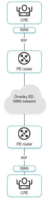
- Using BGP to configure the connectivity of CPE devices within a Kaspersky SD-WAN domain.
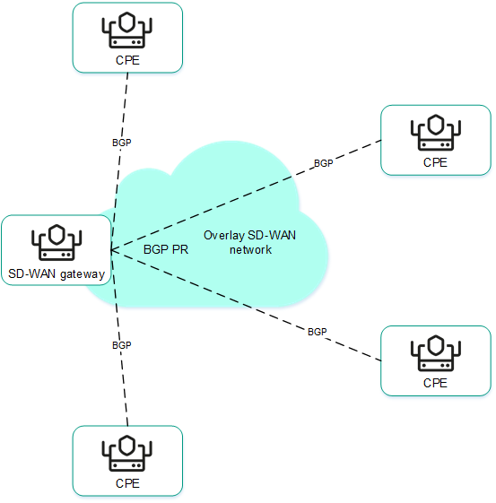
Configuring the BGP protocol
You can specify settings for using the BGP dynamic routing protocol on an individual CPE device or on all devices that use the CPE template. If you plan to use route filtering, you must create route maps before configuring BGP.
Use the following instructions to configure BGP:
- Configuring BGP on an individual CPE device.
To configure BGP on an individual CPE device:
- In the menu, go to the SD-WAN section.
By default, the CPE subsection is displayed with a table of CPE devices.
- Click the CPE device.
The settings area is displayed in the lower part of the page. You can expand the settings area to fill the entire page by clicking the expand button
. - Select the BGP settings tab.
By default, the General settings tab is selected, which displays the BGP settings.
- Select the Override check box to ignore the applied CPE template and make the settings in the selected tab editable. This check box is cleared by default.
- In the BGP drop-down list, select one of the following values:
- Enabled
- Disabled (selected by default)
- In the AS field, enter the number of your autonomous system. Range of values: 1 to 4,294,967,295.
- In the Router ID field, enter the IPv4 address of the CPE device.
- In the Maximum paths field, enter the maximum number of entries in the routing table of the CPE device. Range of values: 1 to 8.
- If necessary, select the following check boxes:
- Select the Always compare MED check box. This check box allows the CPE device to compare the multi-exit discriminator (MED) of routes advertised from different autonomous systems.
You must make sure that this check box is selected or cleared in the same way on all CPE devices in your autonomous system. Otherwise, exchange of routing information may result in routing loops.
- Select the Graceful restart check box to enable on the CPE device.
- Select the Use default IPv4 unicast routes check box to have the CPE device exchange IPv4 routes with BGP peers by default.
By default, all check boxes are cleared.
- Select the Always compare MED check box. This check box allows the CPE device to compare the multi-exit discriminator (MED) of routes advertised from different autonomous systems.
- If necessary, configure BGP timers:
- Select the BGP timers check box. This check box is cleared by default.
- In the Keepalive field, enter the time interval in seconds that the CPE device uses to send keepalive messages to BGP peers. Range of values: 0 to 65,535.
- In the Holdtime field, enter the time in seconds that the CPE device must wait to receive keepalive messages from BGP peers. If no keepalive messages are received from the BGP peer within the specified time, the device considers the peer unavailable. Range of values: 0 to 65,535.
- If necessary, under Route redistribution, configure the redistribution of routes of other routing protocols in BGP:
- Select the check box next to the route type:
- Kernel to redistribute Kernel routes generated by the operating system of the CPE device.
- Connected to redistribute routes directly connected to CPE device interfaces.
- Static to redistribute static routes.
- OSPF to redistribute OSPF routes.
By default, all check boxes are cleared.
- In the Route map drop-down list, select a route map to pick the routes that you want to redistribute.
- In the Metric field, enter a metric for redistributed routes. Range of values: 0 to 16,777,214.
- Select the check box next to the route type:
- If necessary, specify the network that the CPE device must advertise to its BGP peers:
- Under Networks, click + Network.
- In the Network field, enter the IP address and subnet mask.
- In the Route map drop-down list, select a route map for the advertised routes.
You can specify multiple networks.
- In the upper part of the settings area, click Save to save the configuration of the CPE device.
- In the menu, go to the SD-WAN section.
- Configuring BGP on all devices that use a CPE template.
To configure BGP on all devices that use a CPE template:
- In the menu, go to the SD-WAN → CPE templates subsection.
A table of CPE templates is displayed.
- Click the CPE template.
The settings area is displayed in the lower part of the page. You can expand the settings area to fill the entire page by clicking the expand button
. - Select the BGP settings tab.
By default, the General settings tab is selected, which displays the BGP settings.
- In the BGP drop-down list, select one of the following values:
- Enabled
- Disabled (selected by default)
- In the AS field, enter the number of your autonomous system. Range of values: 1 to 4,294,967,295.
- In the Router ID field, enter the IPv4 address of the CPE device.
- In the Maximum paths field, enter the maximum number of entries in the routing table of the CPE device. Range of values: 1 to 8.
- If necessary, select the following check boxes:
- Select the Always compare MED check box. This check box allows the CPE device to compare the multi-exit discriminator (MED) of routes advertised from different autonomous systems.
You must make sure that this check box is selected or cleared in the same way on all CPE devices in your autonomous system. Otherwise, exchange of routing information may result in routing loops.
- Select the Graceful restart check box to enable Graceful restart on the CPE device.
- Select the Use default IPv4 unicast routes check box to have the CPE device exchange IPv4 routes with BGP peers by default.
By default, all check boxes are cleared.
- Select the Always compare MED check box. This check box allows the CPE device to compare the multi-exit discriminator (MED) of routes advertised from different autonomous systems.
- If necessary, configure BGP timers:
- Select the BGP timers check box. This check box is cleared by default.
- In the Keepalive field, enter the time interval in seconds that the CPE device uses to send keepalive messages to BGP peers. Range of values: 0 to 65,535.
- In the Holdtime field, enter the time in seconds that the CPE device must wait to receive keepalive messages from BGP peers. If no keepalive messages are received from the BGP peer within the specified time, the device considers the peer unavailable. Range of values: 0 to 65,535.
- If necessary, under Route redistribution, configure the redistribution of routes of other routing protocols in BGP:
- Select the check box next to the route type:
- Kernel to redistribute Kernel routes generated by the operating system of the CPE device.
- Connected to redistribute routes directly connected to CPE device interfaces.
- Static to redistribute static routes.
- OSPF to redistribute OSPF routes.
By default, all check boxes are cleared.
- In the Route map drop-down list, select a route map to pick the routes that you want to redistribute.
- In the Metric field, enter a metric for redistributed routes. Range of values: 0 to 16,777,214.
- Select the check box next to the route type:
- If necessary, specify the network that the CPE device must advertise to its BGP peers:
- Under Networks, click + Network.
- In the Network field, enter the IP address and subnet mask.
- In the Route map drop-down list, select a route map for the advertised routes.
You can specify multiple networks.
- In the upper part of the settings area, click Save to save the configuration of the CPE template.
- In the menu, go to the SD-WAN → CPE templates subsection.
Creating a BGP peer
You can create a BGP peer on an individual CPE device or on all devices that use the CPE template. The maximum number of dynamic BGP peers is 512. If you plan to use route filtering, before creating a BGP peer, you must do the following:
To create a BGP peer, use the following instructions:
- Creating a BGP peer on an individual CPE device.
To create a BGP peer on an individual CPE device:
- In the menu, go to the SD-WAN section.
By default, the CPE subsection is displayed with a table of CPE devices.
- Click the CPE device.
The settings area is displayed in the lower part of the page. You can expand the settings area to fill the entire page by clicking the expand button
. - Select the BGP settings → Neighbors tab.
A table of BGP peers is displayed.
- Select the Override check box to ignore the applied CPE template and make the settings in the selected tab editable. This check box is cleared by default.
- Click + BGP neighbor.
- This opens a window; in that window, in the Name field, enter the name of the BGP peer. Maximum length: 50 characters.
- If you do not want to establish a TCP session with the BGP peer after it is created, select the Disable BGP peer check box. This check box is cleared by default.
- In the Neighbor IP field, enter the IPv4 address of the BGP peer.
- In the Remote AS field, enter the autonomous system number of the BGP peer. Range of values: 1 to 4 294 967 295.
- If necessary, enter a brief description of the BGP peer in the Description field.
- In the Password field, enter the password for establishing a TCP session with the BGP peer. To see the entered password, you can click the show button . For a TCP session to be successfully established between two BGP peers, they must use the same password.
- In the Loopback interface field, enter the IP address of the loopback interface that the CPE device must send to the BGP peer when establishing a TCP session.
- In the eBGP hops field, enter the number of hops between the CPE device and the BGP peer if the TCP session is not established directly. Range of values: 1 to 255.
- If necessary, configure BGP timers:
- Select the Custom BGP timers check box. This check box is cleared by default.
- In the Keepalive field, enter the time interval in seconds that the CPE device uses to send keepalive messages to BGP peers. Range of values: 0 to 65,535.
- In the Holdtime field, enter the time in seconds that the CPE device must wait to receive keepalive messages from BGP peers. If no keepalive messages are received from the BGP peer within the specified time, the device considers the peer unavailable. Range of values: 0 to 65,535.
- To use the BFD protocol to detect loss of connectivity, select the BFD check box. This check box is cleared by default.
- Select the Advanced settings to specify advanced BGP peer settings.
- If necessary, select the following check boxes:
- Select the Soft-reconfiguration inbound check box to store routes advertised by the BGP peer locally on the CPE device. This check box is cleared by default.
Using this feature reduces the amount of memory available on the device.
- Select the Attribute unchanged AS path check box to prevent modifying the 'AS path' attribute of routes that the CPE device advertises to the BGP peer.
- Select the Allow AS in check box to allow the CPE device to receive from a BGP peer routes with the 'AS path' attribute, the value of which is the autonomous system number of this device.
- Select the Attribute unchanged next-hop check box to prevent modifying the 'next hop' attribute of routes that the CPE device advertises to the BGP peer.
- Select the Next-hop self check box to use the IP address of the CPE device as the 'next-hop' attribute when advertising routes to the BGP peer.
- Select the Attribute unchanged MED check box to prevent modifying the 'MED' attribute of routes that the CPE device advertises to the BGP peer.
- Select the Route reflector client check box to assign the Route Reflector role to the CPE device and the Route Reflector Client role to the BGP peer. You can only select this check box when configuring a BGP peer that is in the same autonomous system as the CPE device.
By default, all check boxes are cleared.
- Select the Soft-reconfiguration inbound check box to store routes advertised by the BGP peer locally on the CPE device. This check box is cleared by default.
- In the Local AS field, enter the number of the local autonomous system that the CPE device must send to the BGP peer. Range of values: 1 to 4 294 967 295.
- In the Weight field, enter the weight of the routes advertised by the BGP peer. The greater the weight of a route, the higher its priority. Range of values: 0 to 65,535.
- In the Maximum prefix field, enter the maximum number of prefixes that the BGP peer can advertise to a CPE device. Range of values: 1 to 4,294,967,295.
- If you want a CPE device to advertise routes with the 'community' attribute to its BGP peer, select the Send community check box and select the type of attribute to be sent in the drop-down list:
- All to send all available types of the 'community' attribute to the BGP peer.
- Standard and extended community to send 'standard community' and 'extended community' attributes to the BGP peer.
- Extended community to send the 'extended community' attribute to the BGP peer.
- Large community to send the 'large community' attribute to the BGP peer.
- Standard community to send the 'standard community' attribute to the BGP peer.
This check box is cleared by default.
- Select the Default originate check box if you want the CPE device to forward the default route (0.0.0.0) to the BGP peer. This check box is cleared by default. You can also select the Set route map check box and select a previously created route map for the default route from the drop-down list that is displayed.
- Select the Filtering tab to configure route filtering for the BGP peer.
- Under Route map, select previously created route maps for route filtering:
- In the Inbound drop-down list, select the route map that the BGP peer must use when advertising routes to the CPE device.
- In the Outbound drop-down list, select the route map that the CPE must use when advertising routes to the BGP peer.
- Under Prefix list, select previously created prefix lists for route filtering:
- In the Inbound drop-down list, select the prefix list that the BGP peer must use when advertising routes to the CPE device.
- In the Outbound drop-down list, select the prefix list that the CPE must use when advertising routes to the BGP peer.
- Under Access control list, select previously created access control lists for route filtering:
- In the Inbound drop-down list, select the access control list that the BGP peer must use when advertising routes to the CPE device.
- In the Outbound drop-down list, select the access control list that the CPE must use when advertising routes to the BGP peer.
- Click Create.
The BGP peer is created and displayed in the table.
- In the upper part of the settings area, click Save to save the configuration of the CPE device.
- In the menu, go to the SD-WAN section.
- Creating a BGP peer on all devices that use the CPE template.
To create a BGP peer on all devices that use the CPE template:
- In the menu, go to the SD-WAN → CPE templates subsection.
A table of CPE templates is displayed.
- Click the CPE template.
The settings area is displayed in the lower part of the page. You can expand the settings area to fill the entire page by clicking the expand button
. - Select the BGP settings → Neighbors tab.
A table of BGP peers is displayed.
- Click + BGP neighbor.
- This opens a window; in that window, in the Name field, enter the name of the BGP peer. Maximum length: 50 characters.
- If you do not want to establish a TCP session with the BGP peer after it is created, select the Disable BGP peer check box. This check box is cleared by default.
- In the Neighbor IP field, enter the IPv4 address of the BGP peer.
- In the Remote AS field, enter the autonomous system number of the BGP peer. Range of values: 1 to 4 294 967 295.
- If necessary, enter a brief description of the BGP peer in the Description field.
- In the Password field, enter the password for establishing a TCP session with the BGP peer. To see the entered password, you can click the show button . For a TCP session to be successfully established between two BGP peers, they must use the same password.
- In the Loopback interface field, enter the IP address of the loopback interface that the CPE device must send to the BGP peer when establishing a TCP session.
- In the eBGP hops field, enter the number of hops between the CPE device and the BGP peer if the TCP session is not established directly. Range of values: 1 to 255.
- If necessary, configure BGP timers:
- Select the Custom BGP timers check box. This check box is cleared by default.
- In the Keepalive field, enter the time interval in seconds that the CPE device uses to send keepalive messages to BGP peers. Range of values: 0 to 65,535.
- In the Holdtime field, enter the time in seconds that the CPE device must wait to receive keepalive messages from BGP peers. If no keepalive messages are received from the BGP peer within the specified time, the device considers the peer unavailable. Range of values: 0 to 65,535.
- To use the BFD protocol to detect loss of connectivity, select the BFD check box. This check box is cleared by default.
- Select the Advanced settings to specify advanced BGP peer settings.
- If necessary, select the following check boxes:
- Select the Soft-reconfiguration inbound check box to store routes advertised by the BGP peer locally on the CPE device. This check box is cleared by default.
Using this feature reduces the amount of memory available on the device.
- Select the Attribute unchanged AS path check box to prevent modifying the 'AS path' attribute of routes that the CPE device advertises to the BGP peer.
- Select the Allow AS in check box to allow the CPE device to receive from a BGP peer routes with the 'AS path' attribute, the value of which is the autonomous system number of this device.
- Select the Attribute unchanged next-hop check box to prevent modifying the 'next hop' attribute of routes that the CPE device advertises to the BGP peer.
- Select the Next-hop self check box to use the IP address of the CPE device as the 'next-hop' attribute when advertising routes to the BGP peer.
- Select the Attribute unchanged MED check box to prevent modifying the 'MED' attribute of routes that the CPE device advertises to the BGP peer.
- Select the Route reflector client check box to assign the Route Reflector role to the CPE device and the Route Reflector Client role to the BGP peer. You can only select this check box when configuring a BGP peer that is in the same autonomous system as the CPE device.
By default, all check boxes are cleared.
- Select the Soft-reconfiguration inbound check box to store routes advertised by the BGP peer locally on the CPE device. This check box is cleared by default.
- In the Local AS field, enter the number of the local autonomous system that the CPE device must send to the BGP peer. Range of values: 1 to 4 294 967 295.
- In the Weight field, enter the weight of the routes advertised by the BGP peer. The greater the weight of a route, the higher its priority. Range of values: 0 to 65,535.
- In the Maximum prefix field, enter the maximum number of prefixes that the BGP peer can advertise to a CPE device. Range of values: 1 to 4,294,967,295.
- If you want a CPE device to advertise routes with the 'community' attribute to its BGP peer, select the Send community check box and select the type of attribute to be sent in the drop-down list:
- All to send all available types of the 'community' attribute to the BGP peer.
- Standard and extended community to send 'standard community' and 'extended community' attributes to the BGP peer.
- Extended community to send the 'extended community' attribute to the BGP peer.
- Large community to send the 'large community' attribute to the BGP peer.
- Standard community to send the 'standard community' attribute to the BGP peer.
This check box is cleared by default.
- Select the Default originate check box if you want the CPE device to forward the default route (0.0.0.0) to the BGP peer. This check box is cleared by default. You can also select the Set route map check box and select a previously created route map for the default route from the drop-down list that is displayed.
- Select the Filtering tab to configure route filtering for the BGP peer.
- Under Route map, select previously created route maps for route filtering:
- In the Inbound drop-down list, select the route map that the BGP peer must use when advertising routes to the CPE device.
- In the Outbound drop-down list, select the route map that the CPE must use when advertising routes to the BGP peer.
- Under Prefix list, select previously created prefix lists for route filtering:
- In the Inbound drop-down list, select the prefix list that the BGP peer must use when advertising routes to the CPE device.
- In the Outbound drop-down list, select the prefix list that the CPE must use when advertising routes to the BGP peer.
- Under Access control list, select previously created access control lists for route filtering:
- In the Inbound drop-down list, select the access control list that the BGP peer must use when advertising routes to the CPE device.
- In the Outbound drop-down list, select the access control list that the CPE must use when advertising routes to the BGP peer.
- Click Create.
The BGP peer is created and displayed in the table.
- In the upper part of the settings area, click Save to save the configuration of the CPE template.
- In the menu, go to the SD-WAN → CPE templates subsection.
Editing a BGP peer
You can edit a BGP peer on an individual CPE device or on all devices that use the CPE template. For a description of the settings, see the instructions for creating a BGP peer.
To edit a BGP peer on an individual CPE device:
- In the menu, go to the SD-WAN section.
By default, the CPE subsection is displayed with a table of CPE devices.
- Click the CPE device.
The settings area is displayed in the lower part of the page. You can expand the settings area to fill the entire page by clicking the expand button
. - Select the BGP settings → Neighbors tab.
A table of BGP peers is displayed.
- Select the Override check box to ignore the applied CPE template and make the settings in the selected tab editable. This check box is cleared by default.
- Click Edit next to the BGP peer.
- This opens a window; in that window, edit the settings that you want to change.
- Click Save.
- In the upper part of the settings area, click Save to save the configuration of the CPE device.
To edit a BGP peer on all devices that use the CPE template:
- In the menu, go to the SD-WAN → CPE templates subsection.
A table of CPE templates is displayed.
- Click the CPE template.
The settings area is displayed in the lower part of the page. You can expand the settings area to fill the entire page by clicking the expand button
. - Select the BGP settings → Neighbors tab.
A table of BGP peers is displayed.
- Click Edit next to the BGP peer.
- This opens a window; in that window, edit the settings that you want to change.
- Click Save.
- In the upper part of the settings area, click Save to save the configuration of the CPE template.
Deleting a BGP peer
You can delete a BGP peer on an individual CPE device or on all devices that use the CPE template. Deleted BGP peers cannot be restored.
To delete a BGP peer on an individual CPE device:
- In the menu, go to the SD-WAN section.
By default, the CPE subsection is displayed with a table of CPE devices.
- Click the CPE device.
The settings area is displayed in the lower part of the page. You can expand the settings area to fill the entire page by clicking the expand button
. - Select the BGP settings → Neighbors tab.
A table of BGP peers is displayed.
- Select the Override check box to ignore the applied CPE template and make the settings in the selected tab editable. This check box is cleared by default.
- Click Delete next to the BGP peer.
- In the confirmation window, click Delete.
The BGP peer is deleted and is no longer displayed in the table.
- In the upper part of the settings area, click Save to save the configuration of the CPE device.
To delete a BGP peer on all devices that use the CPE template:
- In the menu, go to the SD-WAN → CPE templates subsection.
A table of CPE templates is displayed.
- Click the CPE template.
The settings area is displayed in the lower part of the page. You can expand the settings area to fill the entire page by clicking the expand button
. - Select the BGP settings → Neighbors tab.
A table of BGP peers is displayed.
- Click Delete next to the BGP peer.
- In the confirmation window, click Delete.
The BGP peer is deleted and is no longer displayed in the table.
- In the upper part of the settings area, click Save to save the configuration of the CPE template.
Creating a BGP peer group
You can create a BGP peer group on an individual CPE device or on all devices that use the CPE template. If you plan to use route filtering, before creating a BGP peer group, you must do the following:
To create a BGP peer group, use the following instructions:
- Creating a BGP peer group on an individual CPE device.
To create a BGP peer group on an individual CPE device:
- In the menu, go to the SD-WAN section.
By default, the CPE subsection is displayed with a table of CPE devices.
- Click the CPE device.
The settings area is displayed in the lower part of the page. You can expand the settings area to fill the entire page by clicking the expand button
. - Select the BGP settings → Peer groups tab.
A table of BGP peer groups is displayed.
- Select the Override check box to ignore the applied CPE template and make the settings in the selected tab editable. This check box is cleared by default.
- Click + Peer group.
- This opens a window; in that window, in the Name field, enter the name of the BGP peer group. Maximum length: 50 characters.
- If you do not want to establish a TCP session with the BGP peer group after it is created, select the Disable BGP peer group check box. This check box is cleared by default.
- In the BGP range field, enter the IP address range of the BGP peer group. The range is specified using a prefix.
- In the Remote AS field, enter the autonomous system number of the BGP peer group. Range of values: 1 to 4,294,967,295.
- If necessary, enter a brief description of the BGP peer group in the Description field.
- In the Password field, enter the password for establishing a TCP session with the BGP peer group. To see the entered password, you can click the show button . For a TCP session to be successfully established between two BGP peers, they must use the same password.
- In the Loopback interface field, enter the IP address of the loopback interface that the CPE device must send to the BGP peer group when establishing a TCP session.
- In the eBGP hops field, enter the number of hops between the CPE device and the BGP peer group if the TCP session is not established directly. Range of values: 1 to 255.
- If necessary, configure BGP timers:
- Select the Custom BGP timers check box. This check box is cleared by default.
- In the Keepalive field, enter the time interval in seconds that the CPE device uses to send keepalive messages to the BGP peer group. Range of values: 0 to 65,535.
- In the Holdtime field, enter the time in seconds that the CPE device must wait to receive keepalive messages from the BGP peer group. If no keepalive messages are received from the BGP peer within the specified time, the device considers the peer unavailable. Range of values: 0 to 65,535.
- To use the BFD protocol to detect loss of connectivity, select the BFD check box. This check box is cleared by default.
- Select the Advanced settings to specify advanced BGP peer group settings.
- If necessary, select the following check boxes:
- Select the Soft-reconfiguration inbound check box to store routes advertised by the BGP peer group locally on the CPE device.
Using this feature reduces the amount of memory available on the device.
- Select the Attribute unchanged AS path check box to prevent modifying the 'AS path' attribute of routes that the CPE device advertises to the BGP peer group.
- Select the Allow AS in check box to allow the CPE device to receive from a BGP peer group routes with the 'AS path' attribute, the value of which is the autonomous system number of this device.
- Select the Attribute unchanged next-hop check box to prevent modifying the 'next hop' attribute of routes that the CPE device advertises to the BGP peer group.
- Select the Next-hop self check box to use the IP address of the CPE device as the 'next-hop' attribute when advertising routes to the BGP peer group.
- Select the Attribute unchanged MED check box to prevent modifying the 'MED' attribute of routes that the CPE device advertises to the BGP peer group.
- Select the Route reflector client check box to assign the Route Reflector role to the CPE device and the Route Reflector Client role to the BGP peer group. You can only select this check box when configuring a BGP peer group that is in the same autonomous system as the CPE device.
By default, all check boxes are cleared.
- Select the Soft-reconfiguration inbound check box to store routes advertised by the BGP peer group locally on the CPE device.
- In the Local AS field, enter the number of the local autonomous system that the CPE device must send to the BGP peer group. Range of values: 1 to 4,294,967,295.
- In the Weight field, enter the weight of the routes advertised by the BGP peer group. The greater the weight of a route, the higher its priority. Range of values: 0 to 65,535.
- In the Maximum prefix field, enter the maximum number of prefixes that the BGP peer group can advertise to a CPE device. Range of values: 1 to 4,294,967,295.
- If you want a CPE device to advertise routes with the 'community' attribute to the BGP peer group, select the Send community check box and select the type of attribute to be sent in the drop-down list:
- All to send all available types of the 'community' attribute to the BGP peer.
- Standard and extended community to send 'standard community' and 'extended community' attributes to the BGP peer.
- Extended community to send the 'extended community' attribute to the BGP peer.
- Large community to send the 'large community' attribute to the BGP peer.
- Standard community to send the 'standard community' attribute to the BGP peer.
This check box is cleared by default.
- Select the Default originate check box if you want the CPE device to forward the default route (0.0.0.0) to the BGP peer group. This check box is cleared by default. You can also select the Set route map check box and select a previously created route map for the default route from the drop-down list that is displayed.
- Select the Filtering tab to configure route filtering for the BGP peer group.
- Under Route map, select previously created route maps for route filtering:
- In the Inbound drop-down list, select the route map that the BGP peer group must use when advertising routes to the CPE device.
- In the Outbound drop-down list, select the route map that the CPE must use when advertising routes to the BGP peer group.
- Under Prefix list, select previously created prefix lists for route filtering:
- In the Inbound drop-down list, select the prefix list that the BGP peer group must use when advertising routes to the CPE device.
- In the Outbound drop-down list, select the prefix list that the CPE must use when advertising routes to the BGP peer group.
- Under Access control list, select previously created access control lists for route filtering:
- In the Inbound drop-down list, select the access control list that the BGP peer group must use when advertising routes to the CPE device.
- In the Outbound drop-down list, select the access control list that the CPE must use when advertising routes to the BGP peer group.
- Click Create.
The BGP peer group is created and displayed in the table.
- In the upper part of the settings area, click Save to save the configuration of the CPE device.
- In the menu, go to the SD-WAN section.
- Creating a BGP peer group on all devices that use the CPE template.
To create a BGP peer group on all devices that use the CPE template:
- In the menu, go to the SD-WAN → CPE templates subsection.
A table of CPE templates is displayed.
- Click the CPE template.
The settings area is displayed in the lower part of the page. You can expand the settings area to fill the entire page by clicking the expand button
. - Select the BGP settings → Peer groups tab.
A table of BGP peer groups is displayed.
- Click + Peer group.
- This opens a window; in that window, in the Name field, enter the name of the BGP peer group. Maximum length: 50 characters.
- If you do not want to establish a TCP session with the BGP peer group after it is created, select the Disable BGP peer group check box. This check box is cleared by default.
- In the BGP range field, enter the IP address range of the BGP peer group. The range is specified using a prefix.
- In the Remote AS field, enter the autonomous system number of the BGP peer group. Range of values: 1 to 4,294,967,295.
- If necessary, enter a brief description of the BGP peer group in the Description field.
- In the Password field, enter the password for establishing a TCP session with the BGP peer group. To see the entered password, you can click the show button . For a TCP session to be successfully established between two BGP peers, they must use the same password.
- In the Loopback interface field, enter the IP address of the loopback interface that the CPE device must send to the BGP peer group when establishing a TCP session.
- In the eBGP hops field, enter the number of hops between the CPE device and the BGP peer group if the TCP session is not established directly. Range of values: 1 to 255.
- If necessary, configure BGP timers:
- Select the Custom BGP timers check box. This check box is cleared by default.
- In the Keepalive field, enter the time interval in seconds that the CPE device uses to send keepalive messages to the BGP peer group. Range of values: 0 to 65,535.
- In the Holdtime field, enter the time in seconds that the CPE device must wait to receive keepalive messages from the BGP peer group. If no keepalive messages are received from the BGP peer within the specified time, the device considers the peer unavailable. Range of values: 0 to 65,535.
- To use the BFD protocol to detect loss of connectivity, select the BFD check box. This check box is cleared by default.
- Select the Advanced settings to specify advanced BGP peer group settings.
- If necessary, select the following check boxes:
- Select the Soft-reconfiguration inbound check box to store routes advertised by the BGP peer group locally on the CPE device.
Using this feature reduces the amount of memory available on the device.
- Select the Attribute unchanged AS path check box to prevent modifying the 'AS path' attribute of routes that the CPE device advertises to the BGP peer group.
- Select the Allow AS in check box to allow the CPE device to receive from a BGP peer group routes with the 'AS path' attribute, the value of which is the autonomous system number of this device.
- Select the Attribute unchanged next-hop check box to prevent modifying the 'next hop' attribute of routes that the CPE device advertises to the BGP peer group.
- Select the Next-hop self check box to use the IP address of the CPE device as the 'next-hop' attribute when advertising routes to the BGP peer group.
- Select the Attribute unchanged MED check box to prevent modifying the 'MED' attribute of routes that the CPE device advertises to the BGP peer group.
- Select the Route reflector client check box to assign the Route Reflector role to the CPE device and the Route Reflector Client role to the BGP peer group. You can only select this check box when configuring a BGP peer group that is in the same autonomous system as the CPE device.
By default, all check boxes are cleared.
- Select the Soft-reconfiguration inbound check box to store routes advertised by the BGP peer group locally on the CPE device.
- In the Local AS field, enter the number of the local autonomous system that the CPE device must send to the BGP peer group. Range of values: 1 to 4,294,967,295.
- In the Weight field, enter the weight of the routes advertised by the BGP peer group. The greater the weight of a route, the higher its priority. Range of values: 0 to 65,535.
- In the Maximum prefix field, enter the maximum number of prefixes that the BGP peer group can advertise to a CPE device. Range of values: 1 to 4,294,967,295.
- If you want a CPE device to advertise routes with the 'community' attribute to the BGP peer group, select the Send community check box and select the type of attribute to be sent in the drop-down list:
- All to send all available types of the 'community' attribute to the BGP peer.
- Standard and extended community to send 'standard community' and 'extended community' attributes to the BGP peer.
- Extended community to send the 'extended community' attribute to the BGP peer.
- Large community to send the 'large community' attribute to the BGP peer.
- Standard community to send the 'standard community' attribute to the BGP peer.
This check box is cleared by default.
- Select the Default originate check box if you want the CPE device to forward the default route (0.0.0.0) to the BGP peer group. This check box is cleared by default. You can also select the Set route map check box and select a previously created route map for the default route from the drop-down list that is displayed.
- Select the Filtering tab to configure route filtering for the BGP peer group.
- Under Route map, select previously created route maps for route filtering:
- In the Inbound drop-down list, select the route map that the BGP peer group must use when advertising routes to the CPE device.
- In the Outbound drop-down list, select the route map that the CPE must use when advertising routes to the BGP peer group.
- Under Prefix list, select previously created prefix lists for route filtering:
- In the Inbound drop-down list, select the prefix list that the BGP peer group must use when advertising routes to the CPE device.
- In the Outbound drop-down list, select the prefix list that the CPE must use when advertising routes to the BGP peer group.
- Under Access control list, select previously created access control lists for route filtering:
- In the Inbound drop-down list, select the access control list that the BGP peer group must use when advertising routes to the CPE device.
- In the Outbound drop-down list, select the access control list that the CPE must use when advertising routes to the BGP peer group.
- Click Create.
The BGP peer group is created and displayed in the table.
- In the upper part of the settings area, click Save to save the configuration of the CPE template.
- In the menu, go to the SD-WAN → CPE templates subsection.
Editing a BGP peer group
You can edit a BGP peer group on an individual CPE device or on all devices that use the CPE template. For a description of the settings, see the instructions for creating a BGP peer group.
To edit a BGP peer group on an individual CPE device:
- In the menu, go to the SD-WAN section.
By default, the CPE subsection is displayed with a table of CPE devices.
- Click the CPE device.
The settings area is displayed in the lower part of the page. You can expand the settings area to fill the entire page by clicking the expand button
. - Select the BGP settings → Peer groups tab.
A table of BGP peer groups is displayed.
- Select the Override check box to ignore the applied CPE template and make the settings in the selected tab editable. This check box is cleared by default.
- Click Edit next to the BGP peer group.
- This opens a window; in that window, edit the settings that you want to change.
- Click Save.
- In the upper part of the settings area, click Save to save the configuration of the CPE device.
To edit a BGP peer group on all devices that use the CPE template:
- In the menu, go to the SD-WAN → CPE templates subsection.
A table of CPE templates is displayed.
- Click the CPE template.
The settings area is displayed in the lower part of the page. You can expand the settings area to fill the entire page by clicking the expand button
. - Select the BGP settings → Peer groups tab.
A table of BGP peer groups is displayed.
- Click Edit next to the BGP peer group.
- This opens a window; in that window, edit the settings that you want to change.
- Click Save.
- In the upper part of the settings area, click Save to save the configuration of the CPE template.
Deleting a BGP peer group
You can delete a BGP peer group on an individual CPE device or on all devices that use the CPE template. Deleted BGP peer groups cannot be restored.
To delete a BGP peer group on an individual CPE device:
- In the menu, go to the SD-WAN section.
By default, the CPE subsection is displayed with a table of CPE devices.
- Click the CPE device.
The settings area is displayed in the lower part of the page. You can expand the settings area to fill the entire page by clicking the expand button
. - Select the BGP settings → Peer groups tab.
A table of BGP peer groups is displayed.
- Select the Override check box to ignore the applied CPE template and make the settings in the selected tab editable. This check box is cleared by default.
- Click Delete next to the BGP peer group.
- In the confirmation window, click Delete.
The BGP peer group is deleted and is no longer displayed in the table.
- In the upper part of the settings area, click Save to save the configuration of the CPE device.
To delete a BGP peer group on all devices that use the CPE template:
- In the menu, go to the SD-WAN → CPE templates subsection.
A table of CPE templates is displayed.
- Click the CPE template.
The settings area is displayed in the lower part of the page. You can expand the settings area to fill the entire page by clicking the expand button
. - Select the BGP settings → Peer groups tab.
A table of BGP peer groups is displayed.
- Click Delete next to the BGP peer group.
- In the confirmation window, click Delete.
The BGP peer group is deleted and is no longer displayed in the table.
- In the upper part of the settings area, click Save to save the configuration of the CPE template.
The OSPF dynamic routing protocol
Kaspersky SD-WAN supports the use of the OSPF (Open Shortest Path First) dynamic routing protocol to exchange routing information between CPE devices connected to your SD-WAN network, as well as with third-party network devices.
When configuring the protocol, you can create OSPF areas (hereinafter also referred to as areas) and OSPF interfaces (hereinafter also referred to as interfaces).
Configuring the OSPF protocol
You can specify settings for using the OSPF dynamic routing protocol on an individual CPE device or on all devices that use the CPE template. If you plan to use route filtering, before configuring the OSPF protocol, you must do the following:
Use the following instructions to configure OSPF:
- Configuring OSPF on an individual CPE device.
To configure OSPF on an individual CPE device:
- In the menu, go to the SD-WAN section.
By default, the CPE subsection is displayed with a table of CPE devices.
- Click the CPE device.
The settings area is displayed in the lower part of the page. You can expand the settings area to fill the entire page by clicking the expand button
. - Select the OSPF tab.
By default, the General settings tab is selected, which displays the OSPF settings.
- Select the Override check box to ignore the applied CPE template and make the settings in the selected tab editable. This check box is cleared by default.
- In the OSPF drop-down list, select one of the following values:
- Enabled
- Disabled (selected by default)
- In the Router ID field, enter the IPv4 address of the CPE device.
- In the Maximum Paths field, enter the maximum number of entries in the routing table of the CPE device. Range of values: 1 to 16.
- If you want to use the CPE device as a border router (Area Border Router, ABR), in the ABR Type drop-down list, select one of the following values:
- IBM (this implementation is used by default)
- CISCO
- Shortcut
- STANDARD
- In the Auto Cost Reference Bandwidth field, enter the reference bandwidth for calculating the cost of communication channels. The cost is used to determine the best route. You can increase or decrease the reference value to influence the route selection and to give preference to certain communication channels. Range of values: 1 to 4,294,967.
- If you need to switch all interfaces of the CPE device to passive mode, select the Passive Interface Default check box. In passive mode, interfaces do not send OSPF hello packets and do not actively participate in OSPF routing. As a rule, interfaces that do not need routing updates, such as interfaces connected to user devices or networks that are not part of the OSPF domain, are switched to passive mode. This check box is cleared by default.
- If you want to keep an OSPF log, select the Log Adjacency Changes check box. The OSPF log records changes that occur between the CPE device and OSPF peers, such as when a peer goes out of service. This check box lets you track changes, resolve peer-related problems, and gather information about the stability of the OSPF network. This check box is cleared by default.
- If you have selected the Log Adjacency Changes check box, if you want to keep a more detailed OSPF log, select the Detail check box. The more detailed log lets you diagnose individual events involving an OSPF peer, as well as see the sequence of its states changing. This check box is cleared by default.
- If necessary, under Route redistribution, configure the redistribution of routes of other routing protocols in OSPF:
- Select the check box next to the route type:
- BGP to redistribute BGP routes.
- Connected to redistribute routes directly connected to CPE device interfaces.
- Kernel to redistribute Kernel routes generated by the operating system of the CPE device.
- Static to redistribute static routes.
By default, all check boxes are cleared.
- In the Route map drop-down list, select a previously created route map to pick the routes that you want to redistribute.
- In the Metric field, enter a metric for redistributed routes. Range of values: 0 to 16,777,214.
- In the Metric Type drop-down list, select the type of the metric:
- Type 1 (or "internal metric")
- Type 2 (or "external metric")
- Select the Filtering check box and in the Access control list drop-down list, select the previously created access control list that you want to use for reallocating routes. This check box is cleared by default.
- Select the check box next to the route type:
- In the Default Metric field, enter the default metric for all OSPF routes. Range of values: 0 to 16,777,214.
- If necessary, configure the CPE device to advertise the default route to the OSPF network:
- Select the Default Originate check box. This check box is cleared by default.
- Select the Always check box to always advertise the default route, even if it is not in the CPE device's routing table. This check box is cleared by default.
- In the Metric Type drop-down list, select the type of metric for the default route:
- Type 1
- Type 2
- In the Metric field, enter a metric for the default route. Range of values: 0 to 16,777,214.
- In the Route map drop-down list, select a previously created route map for the default route.
- In the Distance field, enter the administrative distance for the OSPF routes. When multiple routes exist to a single destination, provided by different routing protocols, the administrative distance allows you to pick the preferred protocol.
The lower the administrative distance specified for a protocol, the higher the priority its route have. For example, if you want routes OSPF routes to always be preferred over BGP routes, specify the administrative distance of 1 for OSPF and 2 for BGP. Range of values: 1 to 255.
- If necessary, configure the administrative distances of individual OSPF routes:
- Select the Distance OSPF check box. This check box is cleared by default.
- In the External field, enter the administrative distance for routes from external OSPF domains or routing protocols. Range of values: 1 to 255.
- In the Inter-Area field, enter the administrative distance for routes from different areas of the same OSPF domain. Range of values: 1 to 255.
- In the Intra-Area field, enter the administrative distance for routes from the same area. Range of values: 1 to 255.
- If necessary, enable Graceful restart on the CPE device:
- Select the Graceful Restart check box. This check box is cleared by default.
- In the Grace Period (sec.) field, enter the length of time, in seconds, during which the CPE device announces its intention to restart to OSPF peers. Range of values: 1 to 1800.
- If necessary, configure timers for the Shortest Path First (SPF) algorithm calculations:
- Select the Timers Throttle SPF check box. This check box is cleared by default.
- In the Delay (sec.) field, enter the length in seconds of the delay before starting the calculations of the SPF algorithm. Range of values: 0 to 600,000.
- In the Initial Hold-Time (ms.) field, enter the minimum retention time in milliseconds between two calculations of the SPF algorithm. Range of values: 0 to 600,000.
- In the Maximum Hold-Time (ms.) field, enter the maximum retention time in milliseconds between two calculations of the SPF algorithm. Range of values: 0 to 600,000.
- If necessary, configure maximum metrics for link state advertisement (LSA):
- Select the Administrative check box to administratively specify the maximum metric value for LSA of the CPE device.
- Select the On Startup check box to specify the time in seconds for which the maximum metric remains applied to the LSA of the CPE device when the OSPF process is started or restarted, and enter a value in theTimer (sec.) field.
- Select the On Shutdown check box to specify the time in seconds for which that the maximum metric remains applied to the LSA of the CPE device when the OSPF process finishes, and enter a value in the Timer (sec.) field.
- In the upper part of the settings area, click Save to save the configuration of the CPE device.
- In the menu, go to the SD-WAN section.
- Configuring OSPF on all devices that use a CPE template.
To configure OSPF on all devices that use a CPE template:
- In the menu, go to the SD-WAN → CPE templates subsection.
A table of CPE templates is displayed.
- Click the CPE template.
The settings area is displayed in the lower part of the page. You can expand the settings area to fill the entire page by clicking the expand button
. - Select the OSPF tab.
By default, the General settings tab is selected, which displays the OSPF settings.
- In the OSPF drop-down list, select one of the following values:
- Enabled
- Disabled (selected by default)
- In the Router ID field, enter the IPv4 address of the CPE device.
- In the Maximum Paths field, enter the maximum number of entries in the routing table of the CPE device. Range of values: 1 to 16.
- If you want to use the CPE device as a border router (Area Border Router, ABR), in the ABR Type drop-down list, select one of the following values:
- IBM (this implementation is used by default)
- CISCO
- Shortcut
- STANDARD
- In the Auto Cost Reference Bandwidth field, enter the reference bandwidth for calculating the cost of communication channels. The cost is used to determine the best route. You can increase or decrease the reference value to influence the route selection and to give preference to certain communication channels. Range of values: 1 to 4,294,967.
- If you need to switch all interfaces of the CPE device to passive mode, select the Passive Interface Default check box. In passive mode, interfaces do not send OSPF hello packets and do not actively participate in OSPF routing. As a rule, interfaces that do not need routing updates, such as interfaces connected to user devices or networks that are not part of the OSPF domain, are switched to passive mode. This check box is cleared by default.
- If you want to keep an OSPF log, select the Log Adjacency Changes check box. The OSPF log records changes that occur between the CPE device and OSPF peers, such as when a peer goes out of service. This check box lets you track changes, resolve peer-related problems, and gather information about the stability of the OSPF network. This check box is cleared by default.
- If you have selected the Log Adjacency Changes check box, if you want to keep a more detailed OSPF log, select the Detail check box. The more detailed log lets you diagnose individual events involving an OSPF peer, as well as see the sequence of its states changing. This check box is cleared by default.
- If necessary, under Route redistribution, configure the redistribution of routes of other routing protocols in OSPF:
- Select the check box next to the route type:
- BGP to redistribute BGP routes.
- Connected to redistribute routes directly connected to CPE device interfaces.
- Kernel to redistribute Kernel routes generated by the operating system of the CPE device.
- Static to redistribute static routes.
By default, all check boxes are cleared.
- In the Route map drop-down list, select a previously created route map to pick the routes that you want to redistribute.
- In the Metric field, enter a metric for redistributed routes. Range of values: 0 to 16,777,214.
- In the Metric Type drop-down list, select the type of the metric:
- Type 1 (or "internal metric")
- Type 2 (or "external metric")
- Select the Filtering check box and in the Access control list drop-down list, select the previously created access control list that you want to use for reallocating routes. This check box is cleared by default.
- Select the check box next to the route type:
- In the Default Metric field, enter the default metric for all OSPF routes. Range of values: 0 to 16,777,214.
- If necessary, configure the CPE device to advertise the default route to the OSPF network:
- Select the Default Originate check box. This check box is cleared by default.
- Select the Always check box to always advertise the default route, even if it is not in the CPE device's routing table. This check box is cleared by default.
- In the Metric Type drop-down list, select the type of metric for the default route:
- Type 1
- Type 2
- In the Metric field, enter a metric for the default route. Range of values: 0 to 16,777,214.
- In the Route map drop-down list, select a previously created route map for the default route.
- In the Distance field, enter the administrative distance for the OSPF routes. When multiple routes exist to a single destination, provided by different routing protocols, the administrative distance allows you to pick the preferred protocol.
The lower the administrative distance specified for a protocol, the higher the priority its route have. For example, if you want routes OSPF routes to always be preferred over BGP routes, specify the administrative distance of 1 for OSPF and 2 for BGP. Range of values: 1 to 255.
- If necessary, configure the administrative distances of individual OSPF routes:
- Select the Distance OSPF check box. This check box is cleared by default.
- In the External field, enter the administrative distance for routes from external OSPF domains or routing protocols. Range of values: 1 to 255.
- In the Inter-Area field, enter the administrative distance for routes from different areas of the same OSPF domain. Range of values: 1 to 255.
- In the Intra-Area field, enter the administrative distance for routes from the same area. Range of values: 1 to 255.
- If necessary, enable Graceful restart on the CPE device:
- Select the Graceful Restart check box. This check box is cleared by default.
- In the Grace Period (sec.) field, enter the length of time, in seconds, during which the CPE device announces its intention to restart to OSPF peers. Range of values: 1 to 1800.
- If necessary, configure timers for the Shortest Path First (SPF) algorithm calculations:
- Select the Timers Throttle SPF check box. This check box is cleared by default.
- In the Delay (sec.) field, enter the length in seconds of the delay before starting the calculations of the SPF algorithm. Range of values: 0 to 600,000.
- In the Initial Hold-Time (ms.) field, enter the minimum retention time in milliseconds between two calculations of the SPF algorithm. Range of values: 0 to 600,000.
- In the Maximum Hold-Time (ms.) field, enter the maximum retention time in milliseconds between two calculations of the SPF algorithm. Range of values: 0 to 600,000.
- If necessary, configure maximum metrics for link state advertisement (LSA):
- Select the Administrative check box to administratively specify the maximum metric value for LSA of the CPE device.
- Select the On Startup check box to specify the time in seconds for which the maximum metric remains applied to the LSA of the CPE device when the OSPF process is started or restarted, and enter a value in theTimer (sec.) field.
- Select the On Shutdown check box to specify the time in seconds for which that the maximum metric remains applied to the LSA of the CPE device when the OSPF process finishes, and enter a value in the Timer (sec.) field.
- In the upper part of the settings area, click Save to save the configuration of the CPE template.
- In the menu, go to the SD-WAN → CPE templates subsection.
Creating an OSPF area
You can create an OSPF area on an individual CPE device or on all devices that use the CPE template. If you plan to use route filtering, before creating an area, you must do the following:
To create an OSPF area, use the following instructions:
- Creating an OSPF area on an individual CPE device.
To create an OSPF area on an individual CPE device:
- In the menu, go to the SD-WAN section.
By default, the CPE subsection is displayed with a table of CPE devices.
- Click the CPE device.
The settings area is displayed in the lower part of the page. You can expand the settings area to fill the entire page by clicking the expand button
. - Select the OSPF → OSPF Areas tab.
A table of OSPF areas is displayed.
- Select the Override check box to ignore the applied CPE template and make the settings in the selected tab editable. This check box is cleared by default.
- Click + Configure OSPF Area.
- This opens a window; in that window, in the Name field, enter the area ID as an IPv4 address or an integer number.
- If necessary, make the area a stub area:
- Select the Stub check box. This check box is cleared by default.
- In the Area Type drop-down list, select a stub area type:
- Stub
- STUB NO-SUMMARY
- NSSA
- NSSA NO-SUMMARY
- If the Area Type drop-down list, you selectedNSSA or NSSA NO-SUMMARY, if you need to prevent the propagation of the default route to the NSSA area, select the NSSA Suppress FA check box. This check box is cleared by default.
- In the Default Cost field, enter a metric for the default route or for summary routes.
- If you need to use the shortcut method when performing the SPF algorithm calculations, select the Shortcut check box. This method helps reduce the amount of computation by excluding certain areas. This check box is cleared by default.
- In the Authentication drop-down list, select the OSPF authentication method:
- Message Digest to use the MD5 algorithm, which ensures the security of communication by verifying the authenticity of packets using a shared secret key.
- Simple Password to use an unencrypted password. This authentication method is less secure than Message Digest, however, it can provide authentication when used in a trusted network environment.
- If necessary, under OSPF Ranges, add a range of IP addresses and allow or prohibit advertising of addresses from this range in OSPF:
- Click + Range.
- In the Range field, enter a range of IP addresses. The range is specified using a prefix.
- In the Action drop-down list, select the action that you want to apply to IP addresses from the range:
- Advertise to advertise in OSPF. This is the default setting.
- Not Advertise to not advertise in OSPF.
- Substitute to substitute with IP addresses from a different range and advertise in OSPF.
- If the Action drop-down list, you selected Substitute, in the Substitute field, enter the range of IP addresses that you want to substitute the original range with.
- If in the Action drop-down list, you selected Advertise or Substitute, in the Cost field, enter a metric for IP addresses in the range. Range of values: 0 to 16,777,215.
- If necessary, under Virtual Links, add a virtual communication channel to connect the area you are creating to another area through the transit area:
- Click + Virtual Link.
- In the Address field, enter the IPv4 address of the router interface in the transit area.
- If necessary, under Filtering, configure route filtering in OSPF:
- In the Export List drop-down list, select a previously created access control list to filter routes advertised to other areas.
- In the Import List drop-down list, select a previously created access control list to filter routes advertised from other areas.
- In the Outbound Filter List drop-down list, select a previously created prefix list to filter routes advertised to other areas.
- In the Inbound Filter List drop-down list, select a previously created prefix list to filter routes advertised from other areas.
- Click Save.
The OSPF area is created and displayed in the table.
- In the upper part of the settings area, click Save to save the configuration of the CPE device.
- In the menu, go to the SD-WAN section.
- Creating an OSPF area on all devices that use the CPE template.
To create an OSPF area on all devices that use the CPE template:
- In the menu, go to the SD-WAN → CPE templates subsection.
A table of CPE templates is displayed.
- Click the CPE template.
The settings area is displayed in the lower part of the page. You can expand the settings area to fill the entire page by clicking the expand button
. - Select the OSPF → OSPF Areas tab.
A table of OSPF areas is displayed.
- Click + Configure OSPF Area.
- This opens a window; in that window, in the Name field, enter the area ID as an IPv4 address or an integer number.
- If necessary, make the area a stub area:
- Select the Stub check box. This check box is cleared by default.
- In the Area Type drop-down list, select a stub area type:
- Stub
- STUB NO-SUMMARY
- NSSA
- NSSA NO-SUMMARY
- If the Area Type drop-down list, you selectedNSSA or NSSA NO-SUMMARY, if you need to prevent the propagation of the default route to the NSSA area, select the NSSA Suppress FA check box. This check box is cleared by default.
- In the Default Cost field, enter a metric for the default route or for summary routes.
- If you need to use the shortcut method when performing the SPF algorithm calculations, select the Shortcut check box. This method helps reduce the amount of computation by excluding certain areas. This check box is cleared by default.
- In the Authentication drop-down list, select the OSPF authentication method:
- Message Digest to use the MD5 algorithm, which ensures the security of communication by verifying the authenticity of packets using a shared secret key.
- Simple Password to use an unencrypted password. This authentication method is less secure than Message Digest, however, it can provide authentication when used in a trusted network environment.
- If necessary, under OSPF Ranges, add a range of IP addresses and allow or prohibit advertising of addresses from this range in OSPF:
- Click + Range.
- In the Range field, enter a range of IP addresses. The range is specified using a prefix.
- In the Action drop-down list, select the action that you want to apply to IP addresses from the range:
- Advertise to advertise in OSPF. This is the default setting.
- Not Advertise to not advertise in OSPF.
- Substitute to substitute with IP addresses from a different range and advertise in OSPF.
- If the Action drop-down list, you selected Substitute, in the Substitute field, enter the range of IP addresses that you want to substitute the original range with.
- If in the Action drop-down list, you selected Advertise or Substitute, in the Cost field, enter a metric for IP addresses in the range. Range of values: 0 to 16,777,215.
- If necessary, under Virtual Links, add a virtual communication channel to connect the area you are creating to another area through the transit area:
- Click + Virtual Link.
- In the Address field, enter the IPv4 address of the router interface in the transit area.
- If necessary, under Filtering, configure route filtering in OSPF:
- In the Export List drop-down list, select a previously created access control list to filter routes advertised to other areas.
- In the Import List drop-down list, select a previously created access control list to filter routes advertised from other areas.
- In the Outbound Filter List drop-down list, select a previously created prefix list to filter routes advertised to other areas.
- In the Inbound Filter List drop-down list, select a previously created prefix list to filter routes advertised from other areas.
- Click Save.
The OSPF area is created and displayed in the table.
- In the upper part of the settings area, click Save to save the configuration of the CPE template.
- In the menu, go to the SD-WAN → CPE templates subsection.
Editing an OSPF area
You can edit an OSPF area on an individual CPE device or on all devices that use the CPE template. For a description of the settings, see the instructions for creating an area.
To edit an OSPF area on an individual CPE device:
- In the menu, go to the SD-WAN section.
By default, the CPE subsection is displayed with a table of CPE devices.
- Click the CPE device.
The settings area is displayed in the lower part of the page. You can expand the settings area to fill the entire page by clicking the expand button
. - Select the OSPF → OSPF Areas tab.
A table of OSPF areas is displayed.
- Select the Override check box to ignore the applied CPE template and make the settings in the selected tab editable. This check box is cleared by default.
- Click Edit next to the OSPF area.
- This opens a window; in that window, edit the settings that you want to change.
- Click Save.
- In the upper part of the settings area, click Save to save the configuration of the CPE device.
To edit an OSPF area on all devices that use the CPE template:
- In the menu, go to the SD-WAN → CPE templates subsection.
A table of CPE templates is displayed.
- Click the CPE template.
The settings area is displayed in the lower part of the page. You can expand the settings area to fill the entire page by clicking the expand button
. - Select the OSPF → OSPF Areas tab.
A table of OSPF areas is displayed.
- Click Edit next to the OSPF area.
- This opens a window; in that window, edit the settings that you want to change.
- Click Save.
- In the upper part of the settings area, click Save to save the configuration of the CPE template.
Deleting an OSPF area
You can delete an OSPF area on an individual CPE device or on all devices that use the CPE template. Deleted areas cannot be restored.
To delete an OSPF area on an individual CPE device:
- In the menu, go to the SD-WAN section.
By default, the CPE subsection is displayed with a table of CPE devices.
- Click the CPE device.
The settings area is displayed in the lower part of the page. You can expand the settings area to fill the entire page by clicking the expand button
. - Select the OSPF → OSPF Areas tab.
A table of OSPF areas is displayed.
- Select the Override check box to ignore the applied CPE template and make the settings in the selected tab editable. This check box is cleared by default.
- Click Delete next to the OSPF area.
- In the confirmation window, click Delete.
The OSPF area is deleted and is no longer displayed in the table.
- In the upper part of the settings area, click Save to save the configuration of the CPE device.
To delete an OSPF area on all devices that use the CPE template:
- In the menu, go to the SD-WAN section.
By default, the CPE subsection is displayed with a table of CPE devices.
- Click the CPE device.
The settings area is displayed in the lower part of the page. You can expand the settings area to fill the entire page by clicking the expand button
. - Select the OSPF → OSPF Areas tab.
A table of OSPF areas is displayed.
- Click Delete next to the OSPF area.
- In the confirmation window, click Delete.
The OSPF area is deleted and is no longer displayed in the table.
- In the upper part of the settings area, click Save to save the configuration of the CPE template.
Creating an OSPF interface
You can create an OSPF interface on an individual CPE device or on all devices that use the CPE template. OSPF interfaces are created on top of network interfaces, so you must first create a network interface.
To create an OSPF interface, use the following instructions:
- Creating an OSPF interface on an individual CPE device.
To create an OSPF interface on an individual CPE device:
- In the menu, go to the SD-WAN section.
By default, the CPE subsection is displayed with a table of CPE devices.
- Click the CPE device.
The settings area is displayed in the lower part of the page. You can expand the settings area to fill the entire page by clicking the expand button
. - Select the OSPF → OSPF Interfaces tab.
A table of OSPF interfaces is displayed.
- Select the Override check box to ignore the applied CPE template and make the settings in the selected tab editable. This check box is cleared by default.
- Click + Configure OSPF Interface.
- This opens a window, in that window, in the Interface drop-down list, select a previously created network interface on top of which you want to create the OSPF interface.
- In the OSPF Area field, enter the ID of the OSPF area to which the interface belongs, as an IPv4 address or an integer number.
- If necessary, configure OSPF authentication:
- In the Authentication drop-down list, select an authentication method:
- Message Digest to use the MD5 algorithm, which ensures the security of communication by verifying the authenticity of packets using a shared secret key.
- Simple Password to use an unencrypted password. This authentication method is less secure than Message Digest, however, it can provide authentication when used in a trusted network environment.
- If in the Authentication drop-down list, you selected Message Digest, in the Password field, enter an authentication password.
- If in the Authentication drop-down list, you selected Message Digest, follow these steps:
- In the Key ID field, enter the MD5 hash. Range of values: 1 to 255.
- In the Key field, enter the MD5 key.
- In the Authentication drop-down list, select an authentication method:
- In the Cost field enter the metric of the interface. Range of values: 1 to 65,535.
- In the Network Type drop-down list, select the type of the network associated with the interface:
- broadcast
- non-broadcast
- point-to-multipoint
- point-to-point
- In the Priority field, enter the priority of the interface. The CPE device with the highest interface priority becomes the designated router, while the device with the second highest priority becomes the backup designated router.
- If you need to switch the interface to passive mode, select the Passive Interface check box. In passive mode, interfaces do not send OSPF hello packets and do not actively participate in OSPF routing. As a rule, interfaces that do not need routing updates, such as interfaces connected to user devices or networks that are not part of the OSPF domain, are switched to passive mode.
- To use the BFD protocol to detect loss of connectivity, select the BFD check box. This check box is cleared by default.
- If necessary, configure OSPF timers:
- Select the OSPF Timers check box. This check box is cleared by default.
- In the Hello (sec.) field, enter the period, in seconds, of the interface sending hello messages. Range of values: 1 to 65,535.
- In the Dead (sec.) field, enter the time in seconds for which the interface must wait to receive hello messages from OSPF peers. If no hello messages are received from the peer within the specified time, the interface considers the peer unavailable. Range of values: 1 to 65,535.
- In the Retransmit Interval (sec.) field, enter the time after which lost packets must be resent. Range of values: 1 to 65,535.
- In the Transmit Delay (sec.) field, enter the delay in seconds before the first OSPF packet is sent. Range of values: 1 to 65,535.
- Click Save.
The OSPF interface is created and displayed in the table.
- In the upper part of the settings area, click Save to save the configuration of the CPE device.
- In the menu, go to the SD-WAN section.
- Creating an OSPF interface on all devices that use the CPE template.
To create an OSPF interface on all devices that use the CPE template:
- In the menu, go to the SD-WAN section.
By default, the CPE subsection is displayed with a table of CPE devices.
- Click the CPE device.
The settings area is displayed in the lower part of the page. You can expand the settings area to fill the entire page by clicking the expand button
. - Select the OSPF → OSPF Interfaces tab.
A table of OSPF interfaces is displayed.
- Click + Configure OSPF Interface.
- This opens a window, in that window, in the Interface drop-down list, select a previously created network interface on top of which you want to create the OSPF interface.
- In the OSPF Area field, enter the ID of the OSPF area to which the interface belongs, as an IPv4 address or an integer number.
- If necessary, configure OSPF authentication:
- In the Authentication drop-down list, select an authentication method:
- Message Digest to use the MD5 algorithm, which ensures the security of communication by verifying the authenticity of packets using a shared secret key.
- Simple Password to use an unencrypted password. This authentication method is less secure than Message Digest, however, it can provide authentication when used in a trusted network environment.
- If in the Authentication drop-down list, you selected Message Digest, in the Password field, enter an authentication password.
- If in the Authentication drop-down list, you selected Message Digest, follow these steps:
- In the Key ID field, enter the MD5 hash. Range of values: 1 to 255.
- In the Key field, enter the MD5 key.
- In the Authentication drop-down list, select an authentication method:
- In the Cost field enter the metric of the interface. Range of values: 1 to 65,535.
- In the Network Type drop-down list, select the type of the network associated with the interface:
- broadcast
- non-broadcast
- point-to-multipoint
- point-to-point
- In the Priority field, enter the priority of the interface. The CPE device with the highest interface priority becomes the designated router, while the device with the second highest priority becomes the backup designated router.
- If you need to switch the interface to passive mode, select the Passive Interface check box. In passive mode, interfaces do not send OSPF hello packets and do not actively participate in OSPF routing. As a rule, interfaces that do not need routing updates, such as interfaces connected to user devices or networks that are not part of the OSPF domain, are switched to passive mode.
- To use the BFD protocol to detect loss of connectivity, select the BFD check box. This check box is cleared by default.
- If necessary, configure OSPF timers:
- Select the OSPF Timers check box. This check box is cleared by default.
- In the Hello (sec.) field, enter the period, in seconds, of the interface sending hello messages. Range of values: 1 to 65,535.
- In the Dead (sec.) field, enter the time in seconds for which the interface must wait to receive hello messages from OSPF peers. If no hello messages are received from the peer within the specified time, the interface considers the peer unavailable. Range of values: 1 to 65,535.
- In the Retransmit Interval (sec.) field, enter the time after which lost packets must be resent. Range of values: 1 to 65,535.
- In the Transmit Delay (sec.) field, enter the delay in seconds before the first OSPF packet is sent. Range of values: 1 to 65,535.
- Click Save.
The OSPF interface is created and displayed in the table.
- In the upper part of the settings area, click Save to save the configuration of the CPE template.
- In the menu, go to the SD-WAN section.
Editing an OSPF interface
You can edit an OSPF interface on an individual CPE device or on all devices that use the CPE template. For a description of the settings, see the instructions for creating a interface.
To edit an OSPF interface on an individual CPE device:
- In the menu, go to the SD-WAN section.
By default, the CPE subsection is displayed with a table of CPE devices.
- Click the CPE device.
The settings area is displayed in the lower part of the page. You can expand the settings area to fill the entire page by clicking the expand button
. - Select the OSPF → OSPF Interfaces tab.
A table of OSPF interfaces is displayed.
- Select the Override check box to ignore the applied CPE template and make the settings in the selected tab editable. This check box is cleared by default.
- Click Edit next to the OSPF interface.
- This opens a window; in that window, edit the settings that you want to change.
- Click Save.
- In the upper part of the settings area, click Save to save the configuration of the CPE device.
To edit an OSPF interface on all devices that use the CPE template:
- In the menu, go to the SD-WAN → CPE templates subsection.
A table of CPE templates is displayed.
- Click the CPE template.
The settings area is displayed in the lower part of the page. You can expand the settings area to fill the entire page by clicking the expand button
. - Select the OSPF → OSPF Interfaces tab.
A table of OSPF interfaces is displayed.
- Click Edit next to the OSPF interface.
- This opens a window; in that window, edit the settings that you want to change.
- Click Save.
- In the upper part of the settings area, click Save to save the configuration of the CPE template.
Deleting an OSPF interface
You can delete an OSPF interface on an individual CPE device or on all devices that use the CPE template. Deleted interfaces cannot be restored.
To delete an OSPF interface on an individual CPE device:
- In the menu, go to the SD-WAN section.
By default, the CPE subsection is displayed with a table of CPE devices.
- Click the CPE device.
The settings area is displayed in the lower part of the page. You can expand the settings area to fill the entire page by clicking the expand button
. - Select the OSPF → OSPF Interfaces tab.
A table of OSPF interfaces is displayed.
- Select the Override check box to ignore the applied CPE template and make the settings in the selected tab editable. This check box is cleared by default.
- Click Delete next to the OSPF interface.
- In the confirmation window, click Delete.
The OSPF interface is deleted and is no longer displayed in the table.
- In the upper part of the settings area, click Save to save the configuration of the CPE device.
To delete an OSPF interface on all devices that use the CPE template:
- In the menu, go to the SD-WAN → CPE templates subsection.
A table of CPE templates is displayed.
- Click the CPE template.
The settings area is displayed in the lower part of the page. You can expand the settings area to fill the entire page by clicking the expand button
. - Select the OSPF → OSPF Interfaces tab.
A table of OSPF interfaces is displayed.
- Click Delete next to the OSPF interface.
- In the confirmation window, click Delete.
The OSPF interface is deleted and is no longer displayed in the table.
- In the upper part of the settings area, click Save to save the configuration of the CPE template.
The BFD protocol
Kaspersky SD-WAN supports the use of the Bidirectional Forwarding Detection (BFD) protocol for fast (within one second) detection of network connectivity problems on data channels and links. When a problem is detected, BFD relays information about the problem from the
to the control plane.Between BFD peers, a BFD session is established, as part of which they exchange control packets to detect network connectivity problems. If a problem with network connectivity occurs during a BFD session, the routing protocol session is terminated on the corresponding interface of the CPE device, and routing tables are subsequently rebuilt.
Enabling or disabling the BFD protocol
You can enable or disable the BFD protocol on an individual CPE device or on all devices that use the CPE template. When enabling the BFD protocol, you must create a BFD peer.
To enable or disable the BFD protocol on an individual CPE device:
- In the menu, go to the SD-WAN section.
By default, the CPE subsection is displayed with a table of CPE devices.
- Click the CPE device.
The settings area is displayed in the lower part of the page. You can expand the settings area to fill the entire page by clicking the expand button
. - Select the BFD settings tab.
A table of BFD peers is displayed.
- Select the Override check box to ignore the applied CPE template and make the settings in the selected tab editable. This check box is cleared by default.
- In the BFD drop-down list, select one of the following values:
- Enabled
- Disabled (selected by default)
- In the upper part of the settings area, click Save to save the configuration of the CPE device.
To enable or disable the BFD protocol on all devices that use a CPE template:
- In the menu, go to the SD-WAN → CPE templates subsection.
A table of CPE templates is displayed.
- Click the CPE template.
The settings area is displayed in the lower part of the page. You can expand the settings area to fill the entire page by clicking the expand button
. - Select the BFD settings tab.
A table of BFD peers is displayed.
- In the BFD drop-down list, select one of the following values:
- Enabled
- Disabled (selected by default)
- In the upper part of the settings area, click Save to save the configuration of the CPE template.
Creating a BFD peer
You can create a BFD peer on an individual CPE device or on all devices that use the CPE template. To create a BFD peer, use the following instructions:
- Creating a BFD peer on an individual CPE device.
To create a BFD peer on an individual CPE device:
- In the menu, go to the SD-WAN section.
By default, the CPE subsection is displayed with a table of CPE devices.
- Click the CPE device.
The settings area is displayed in the lower part of the page. You can expand the settings area to fill the entire page by clicking the expand button
. - Select the BFD settings tab.
A table of BFD peers is displayed.
- Select the Override check box to ignore the applied CPE template and make the settings in the selected tab editable. This check box is cleared by default.
- Click + BFD peer.
- This opens a window; in that window, in the Name field, enter the name of the BFD peer. Maximum length: 255 characters.
- In the IP address field, enter the IP address of the BFD peer.
- In the Transmit interval (msec.) field, enter the time interval in milliseconds for sending control packets to the BFD peer. Range of values: 60 to 10,000.
- In the Receive interval (msec.) field, enter the time interval in milliseconds for receiving control packets from the BFD peer. Range of values: 60 to 10,000.
- In the Multiplier enter the multiplier of the time interval for sending control packets specified in the BFD peer settings. This multiplier is used to determine the time after which a BFD session must be terminated if the BFD peer stops sending control packets. Range of values: 2 to 255.
For example, if the time interval for sending control packets in the BFD peer settings is 200 milliseconds, and you specify a multiplier of 2, the BFD session is terminated after 400 milliseconds, provided that the CPE device has not received a single control packet in that time period.
- Click Create.
The BFD peer is created and displayed in the table.
- In the upper part of the settings area, click Save to save the configuration of the CPE device.
- In the menu, go to the SD-WAN section.
- Creating a BFD peer on all devices that use the CPE template.
To create a BFD peer on all devices that use the CPE template:
- In the menu, go to the SD-WAN → CPE templates subsection.
A table of CPE templates is displayed.
- Click the CPE template.
The settings area is displayed in the lower part of the page. You can expand the settings area to fill the entire page by clicking the expand button
. - Select the BFD settings tab.
A table of BFD peers is displayed.
- Click + BFD peer.
- This opens a window; in that window, in the Name field, enter the name of the BFD peer. Maximum length: 255 characters.
- In the IP address field, enter the IP address of the BFD peer.
- In the Transmit interval (msec.) field, enter the time interval in milliseconds for sending control packets to the BFD peer. Range of values: 60 to 10,000.
- In the Receive interval (msec.) field, enter the time interval in milliseconds for receiving control packets from the BFD peer. Range of values: 60 to 10,000.
- In the Multiplier enter the multiplier of the time interval for sending control packets specified in the BFD peer settings. This multiplier is used to determine the time after which a BFD session must be terminated if the BFD peer stops sending control packets. Range of values: 2 to 255.
For example, if the time interval for sending control packets in the BFD peer settings is 200 milliseconds, and you specify a multiplier of 2, the BFD session is terminated after 400 milliseconds, provided that the CPE device has not received a single control packet in that time period.
- Click Create.
The BFD peer is created and displayed in the table.
- In the upper part of the settings area, click Save to save the configuration of the CPE template.
- In the menu, go to the SD-WAN → CPE templates subsection.
Editing a BFD peer
You can edit a BFD peer on an individual CPE device or on all devices that use the CPE template. For a description of the settings, see the instructions for creating a BFD peer.
To edit a BFD peer on an individual CPE device:
- In the menu, go to the SD-WAN section.
By default, the CPE subsection is displayed with a table of CPE devices.
- Click the CPE device.
The settings area is displayed in the lower part of the page. You can expand the settings area to fill the entire page by clicking the expand button
. - Select the BFD settings tab.
A table of BFD peers is displayed.
- Select the Override check box to ignore the applied CPE template and make the settings in the selected tab editable. This check box is cleared by default.
- Click Edit next to the BFD peer.
- This opens a window; in that window, edit the settings that you want to change.
- Click Save.
- In the upper part of the settings area, click Save to save the configuration of the CPE device.
To edit a BFD peer on all devices that use the CPE template:
- In the menu, go to the SD-WAN → CPE templates subsection.
A table of CPE templates is displayed.
- Click the CPE template.
The settings area is displayed in the lower part of the page. You can expand the settings area to fill the entire page by clicking the expand button
. - Select the BFD settings tab.
A table of BFD peers is displayed.
- Click Edit next to the BFD peer.
- This opens a window; in that window, edit the settings that you want to change.
- Click Save.
- In the upper part of the settings area, click Save to save the configuration of the CPE template.
Deleting a BFD peer
You can delete a BFD peer in the configuration on an individual CPE device or on all devices that use the CPE template. Deleted BFD peers cannot be restored.
To delete a BFD peer on an individual CPE device:
- In the menu, go to the SD-WAN section.
By default, the CPE subsection is displayed with a table of CPE devices.
- Click the CPE device.
The settings area is displayed in the lower part of the page. You can expand the settings area to fill the entire page by clicking the expand button
. - Select the BFD settings tab.
A table of BFD peers is displayed.
- Select the Override check box to ignore the applied CPE template and make the settings in the selected tab editable. This check box is cleared by default.
- Click Delete next to the BFD peer.
- This opens a window; in that window, click Delete.
The BFD peer is deleted and is no longer displayed in the table.
- In the upper part of the settings area, click Save to save the configuration of the CPE device.
To delete a BFD peer on all devices that use the CPE template:
- In the menu, go to the SD-WAN → CPE templates subsection.
A table of CPE templates is displayed.
- Click the CPE template.
The settings area is displayed in the lower part of the page. You can expand the settings area to fill the entire page by clicking the expand button
. - Select the BFD settings tab.
A table of BFD peers is displayed.
- Click Delete next to the BFD peer.
- This opens a window; in that window, click Delete.
The BFD peer is deleted and is no longer displayed in the table.
- In the upper part of the settings area, click Save to save the configuration of the CPE template.
Creating or deleting a static IPv4 route
Kaspersky SD-WAN supports the use of static IPv4 routes for exchange of traffic packets between CPE devices and other routers without using routing protocols.
You can create a static route on an individual CPE device or on all devices that use the CPE template. Before creating a static IPv4 route, you must create a network interface. To create a static route, use the following instructions:
- Creating a static IPv4 route on an individual CPE device.
To create a static IPv4 route on an individual CPE device:
- In the menu, go to the SD-WAN section.
By default, the CPE subsection is displayed with a table of CPE devices.
- Click the CPE device.
The settings area is displayed in the lower part of the page. You can expand the settings area to fill the entire page by clicking the expand button
. - Select the Static routes tab.
A list of static routes is displayed.
- Select the Override check box to ignore the applied CPE template and make the settings in the selected tab editable. This check box is cleared by default.
- Click the create static route button .
- In the Interface drop-down list, select the previously created network interface for sending traffic packets to the destination host.
- In the Target field, enter the IP address of the destination host.
- In the IPv4 netmask field, enter the subnet mask of the destination host.
- In the Gateway field, enter the IP address of the gateway for routing traffic.
- In the Metric field, enter a metric for the route. The default setting is
0. - In the MTU field, enter the MTU value for the route.
- In the Type drop-down list, select the type of the route:
- unicast for a standard route to the destination host. This is the default setting.
- local for a route that is added to the local routing table of the CPE device and is used for IP addresses of local destination hosts.
- broadcast for a route that is added to the local routing table of the CPE device and is used by devices of the OSI data link layer that support the use of broadcast addresses.
- multicast for a route that is used to distribute multicast traffic.
- unreachable for a route to an unreachable destination host. When packets are sent along this route, they are dropped with the
Host UnreachableICMP message. Local senders receive anEHOSTUNREACHerror. - prohibit for a route to an unreachable destination host. When packets are sent along this route, they are dropped with the
Communication Administratively ProhibitedICMP message. Local senders receive anEACCESerror. - blackhole for a route to an unreachable destination host. When packets are sent along this route, they are dropped without sending any messages. Local users receive an
EINVALerror. - anycast for a route to multiple destination hosts that have anycast addresses. Such addresses cannot be used as source addresses of traffic packets.
- In the upper part of the settings area, click Save to save the configuration of the CPE device.
- In the menu, go to the SD-WAN section.
- Creating a static IPv4 route on all devices that use the CPE template.
To create a static IPv4 route peer on all devices that use the CPE template:
- In the menu, go to the SD-WAN → CPE templates subsection.
A table of CPE templates is displayed.
- Click the CPE template.
The settings area is displayed in the lower part of the page. You can expand the settings area to fill the entire page by clicking the expand button
. - Select the Static routes tab.
A list of static routes is displayed.
- Click the create static route button .
- In the Interface drop-down list, select the previously created network interface for sending traffic packets to the destination host.
- In the Target field, enter the IP address of the destination host.
- In the IPv4 netmask field, enter the subnet mask of the destination host.
- In the Gateway field, enter the IP address of the gateway for routing traffic.
- In the Metric field, enter a metric for the route. The default setting is
0. - In the MTU field, enter the MTU value for the route.
- In the Type drop-down list, select the type of the route:
- unicast for a standard route to the destination host. This is the default setting.
- local for a route that is added to the local routing table of the CPE device and is used for IP addresses of local destination hosts.
- broadcast for a route that is added to the local routing table of the CPE device and is used by devices of the OSI data link layer that support the use of broadcast addresses.
- multicast for a route that is used to distribute multicast traffic.
- unreachable for a route to an unreachable destination host. When packets are sent along this route, they are dropped with the
Host UnreachableICMP message. Local senders receive anEHOSTUNREACHerror. - prohibit for a route to an unreachable destination host. When packets are sent along this route, they are dropped with the
Communication Administratively ProhibitedICMP message. Local senders receive anEACCESerror. - blackhole for a route to an unreachable destination host. When packets are sent along this route, they are dropped without sending any messages. Local users receive an
EINVALerror. - anycast for a route to multiple destination hosts that have anycast addresses. Such addresses cannot be used as source addresses of traffic packets.
- In the upper part of the settings area, click Save to save the configuration of the CPE template.
- In the menu, go to the SD-WAN → CPE templates subsection.
If necessary, you can delete a static route on an individual CPE device or on all devices that use the CPE template. Deleted static routes cannot be restored. To delete a static route, use the following instructions:
- Deleting a static route on an individual CPE device.
To delete a static IPv4 route on an individual CPE device:
- In the menu, go to the SD-WAN section.
By default, the CPE subsection is displayed with a table of CPE devices.
- Click the CPE device.
The settings area is displayed in the lower part of the page. You can expand the settings area to fill the entire page by clicking the expand button
. - Select the Static routes tab.
A list of static routes is displayed.
- Select the Override check box to ignore the applied CPE template and make the settings in the selected tab editable. This check box is cleared by default.
- Click the delete button
 next to the static IPv4 route.
The static route is deleted and is no longer displayed in the table.
- In the upper part of the settings area, click Save to save the configuration of the CPE device.
- In the menu, go to the SD-WAN section.
- Deleting a static route on all devices that use the CPE template.
To delete a static IPv4 route peer on all devices that use the CPE template:
- In the menu, go to the SD-WAN → CPE templates subsection.
A table of CPE templates is displayed.
- Click the CPE template.
The settings area is displayed in the lower part of the page. You can expand the settings area to fill the entire page by clicking the expand button
. - Select the Static routes tab.
A list of static routes is displayed.
- Click the delete button next to the static IPv4 route.
The static route is deleted and is no longer displayed in the table.
- In the upper part of the settings area, click Save to save the configuration of the CPE template.
- In the menu, go to the SD-WAN → CPE templates subsection.
The VRRP protocol
Kaspersky SD-WAN supports installing CPE devices at on locations to ensure high availability of these locations. One option for organizing high availability is to use the Virtual Router Redundancy Protocol (VRRP). You can configure VRRP between multiple CPE devices, or between a device and a third-party router.
When configuring VRRP, you must create VRRP instances that specify which CPE devices are combined into virtual routers for high availability.
Each VRRP instance is created with general VRRP settings such as the Virtual Router Identifier (VRID) and the virtual IP address for the network interface of the CPE device.
VRRP instances can be combined into groups to synchronize their operation. In this way, if a change to the primary VRRP router occurs in one of the VRRP instances within the group, the same change is also applied to all other VRRP instances in the group.
Enabling or disabling the VRRP protocol
You can enable or disable the VRRP protocol on an individual CPE device or on all devices that use the CPE template. When you enable VRRP, you must create a VRRP instance.
To enable or disable the VRRP protocol on an individual CPE device:
- In the menu, go to the SD-WAN section.
By default, the CPE subsection is displayed with a table of CPE devices.
- Click the CPE device.
The settings area is displayed in the lower part of the page. You can expand the settings area to fill the entire page by clicking the expand button
. - Select the VRRP tab.
A table of VRPP instances is displayed.
- Select the Override check box to ignore the applied CPE template and make the settings in the selected tab editable. This check box is cleared by default.
- In the VRRP drop-down list, select one of the following values:
- Enabled
- Disabled (selected by default)
- In the upper part of the settings area, click Save to save the configuration of the CPE device.
To enable or disable the VRRP protocol on all devices that use a CPE template:
- In the menu, go to the SD-WAN → CPE templates subsection.
A table of CPE templates is displayed.
- Click the CPE template.
The settings area is displayed in the lower part of the page. You can expand the settings area to fill the entire page by clicking the expand button
. - Select the VRRP tab.
A table of VRPP instances is displayed.
- In the VRRP drop-down list, select one of the following values:
- Enabled
- Disabled (selected by default)
- In the upper part of the settings area, click Save to save the configuration of the CPE template.
Creating a VRRP instance
You can create a VRRP instance on an individual CPE device or on all devices that use the CPE template. Before creating a VRRP instance, you must create a network interface. To create a VRRP instance, use the following instructions:
- Creating a VRRP instance on an individual CPE device.
To create a VRRP instance on an individual CPE device:
- In the menu, go to the SD-WAN section.
By default, the CPE subsection is displayed with a table of CPE devices.
- Click the CPE device.
The settings area is displayed in the lower part of the page. You can expand the settings area to fill the entire page by clicking the expand button
. - Select the VRRP tab.
A table of VRPP instances is displayed.
- Select the Override check box to ignore the applied CPE template and make the settings in the selected tab editable. This check box is cleared by default.
- Click + VRRP instance.
- This opens a window; in that window, in the Name field, enter the name of the VRRP instance. Maximum length: 16 characters.
- In the VRID field, enter the Virtual Router Identifier for the CPE device. You must specify the same VRID for all devices that you want to combine into a virtual router. Range of values: 1 to 255.
- In the Interface drop-down list, select a previously created network interface to which you want to assign a virtual IP address.
- In the VIP field, enter the virtual IP address for the network interface. You must assign the same virtual IP address to the network interfaces of all CPE devices that you want to combine into a virtual router.
- In the State drop-down list, select the role of the CPE device:
- Backup for a backup VRRP router. This is the default setting.
- Master for the primary VRRP router.
- In the Priority field, enter the priority of the VRRP router. The higher the value in this field, the higher the priority. When the primary VRRP router fails, it is replaced by the backup VRRP router with the highest priority. If the backup VRPP router has a higher priority than the primary router, it also becomes the primary router. Range of values: 1 to 1000. The default setting is
100. - In the Advertise interval (sec.) field, enter the time interval in seconds for sending VRRP advertisements. Range of values: 1 to 60. The default setting is
5. - If you do not want to change the role of the backup VRRP router that has become the primary router, even if the old primary VRRP router becomes operational again, select the Nopreempt check box. This check box is cleared by default.
- If necessary, configure sending VRRP advertisements as unicast messages:
- Select the Unicast check box. This check box is cleared by default.
- In the Main VRPP router IP field, enter the necessary value.
- In the Backup VRRP router IP field, enter the necessary value.
- If necessary, use a password for authenticating VRRP advertisements:
- Select the Authentication check box. This check box is cleared by default.
- Enter a password in the field that is displayed. Maximum length of the password: 16 characters. To see the entered password, you can click the show button .
- Click Create.
The VRRP instance is created and displayed in the table.
- In the upper part of the settings area, click Save to save the configuration of the CPE device.
- In the menu, go to the SD-WAN section.
- Creating a VRRP instance on all devices that use the CPE template.
To create a VRRP instance on all devices that use the CPE template:
- In the menu, go to the SD-WAN → CPE templates subsection.
A table of CPE templates is displayed.
- Click the CPE template.
The settings area is displayed in the lower part of the page. You can expand the settings area to fill the entire page by clicking the expand button
. - Select the VRRP tab.
A table of VRPP instances is displayed.
- Click + VRRP instance.
- This opens a window; in that window, in the Name field, enter the name of the VRRP instance. Maximum length: 16 characters.
- In the VRID field, enter the Virtual Router Identifier for the CPE device. You must specify the same VRID for all devices that you want to combine into a virtual router. Range of values: 1 to 255.
- In the Interface drop-down list, select a previously created network interface to which you want to assign a virtual IP address.
- In the VIP field, enter the virtual IP address for the network interface. You must assign the same virtual IP address to the network interfaces of all CPE devices that you want to combine into a virtual router.
- In the State drop-down list, select the role of the CPE device:
- Backup for a backup VRRP router. This is the default setting.
- Master for the primary VRRP router.
- In the Priority field, enter the priority of the VRRP router. The higher the value in this field, the higher the priority. When the primary VRRP router fails, it is replaced by the backup VRRP router with the highest priority. If the backup VRPP router has a higher priority than the primary router, it also becomes the primary router. Range of values: 1 to 1000. The default setting is
100. - In the Advertise interval (sec.) field, enter the time interval in seconds for sending VRRP advertisements. Range of values: 1 to 60. The default setting is
5. - If you do not want to change the role of the backup VRRP router that has become the primary router, even if the old primary VRRP router becomes operational again, select the Nopreempt check box. This check box is cleared by default.
- If necessary, configure sending VRRP advertisements as unicast messages:
- Select the Unicast check box. This check box is cleared by default.
- In the Main VRPP router IP field, enter the necessary value.
- In the Backup VRRP router IP field, enter the necessary value.
- If necessary, use a password for authenticating VRRP advertisements:
- Select the Authentication check box. This check box is cleared by default.
- Enter a password in the field that is displayed. Maximum length of the password: 16 characters. To see the entered password, you can click the show button .
- Click Create.
The VRRP instance is created and displayed in the table.
- In the upper part of the settings area, click Save to save the configuration of the CPE template.
- In the menu, go to the SD-WAN → CPE templates subsection.
Editing a VRRP instance
You can edit a VRRP instance on an individual CPE device or on all devices that use the CPE template. For a description of the settings, see the instructions for creating a VRRP instance.
To edit a VRRP instance on an individual CPE device:
- In the menu, go to the SD-WAN section.
By default, the CPE subsection is displayed with a table of CPE devices.
- Click the CPE device.
The settings area is displayed in the lower part of the page. You can expand the settings area to fill the entire page by clicking the expand button
. - Select the VRRP tab.
A table of VRPP instances is displayed.
- Select the Override check box to ignore the applied CPE template and make the settings in the selected tab editable. This check box is cleared by default.
- Click Edit next to the VRRP instance.
- This opens a window; in that window, edit the settings that you want to change.
- Click Save.
- In the upper part of the settings area, click Save to save the configuration of the CPE device.
To edit a VRRP instance on all devices that use the CPE template:
- In the menu, go to the SD-WAN → CPE templates subsection.
A table of CPE templates is displayed.
- Click the CPE template.
The settings area is displayed in the lower part of the page. You can expand the settings area to fill the entire page by clicking the expand button
. - Select the VRRP tab.
A table of VRPP instances is displayed.
- Click Edit next to the VRRP instance.
- This opens a window; in that window, edit the settings that you want to change.
- Click Save.
- In the upper part of the settings area, click Save to save the configuration of the CPE template.
Deleting a VRRP instance
You can delete a VRRP instance on an individual CPE device or on all devices that use the CPE template. Deleted VRRP instances cannot be restored.
To delete a VRRP instance on an individual CPE device:
- In the menu, go to the SD-WAN section.
By default, the CPE subsection is displayed with a table of CPE devices.
- Click the CPE device.
The settings area is displayed in the lower part of the page. You can expand the settings area to fill the entire page by clicking the expand button
. - Select the VRRP tab.
A table of VRPP instances is displayed.
- Select the Override check box to ignore the applied CPE template and make the settings in the selected tab editable. This check box is cleared by default.
- Click Delete next to the VRRP instance.
- In the confirmation window, click Delete.
The VRRP instance is deleted and is no longer displayed in the table.
- In the upper part of the settings area, click Save to save the configuration of the CPE device.
To delete a VRRP instance on all devices that use the CPE template:
- In the menu, go to the SD-WAN → CPE templates subsection.
A table of CPE templates is displayed.
- Click the CPE template.
The settings area is displayed in the lower part of the page. You can expand the settings area to fill the entire page by clicking the expand button
. - Select the VRRP tab.
A table of VRPP instances is displayed.
- Click Delete next to the VRRP instance.
- In the confirmation window, click Delete.
The VRRP instance is deleted and is no longer displayed in the table.
- In the upper part of the settings area, click Save to save the configuration of the CPE template.
Creating a group of VRRP instances
You can create a VRRP instance group on an individual CPE device or on all devices that use the CPE template. Before creating a VRRP instance group, you must create at least one VRRP instance.
To create a VRRP instance group on an individual CPE device:
- In the menu, go to the SD-WAN section.
By default, the CPE subsection is displayed with a table of CPE devices.
- Click the CPE device.
The settings area is displayed in the lower part of the page. You can expand the settings area to fill the entire page by clicking the expand button
. - Select the VRRP → VRRP instance groups tab.
A table of VRRP instance groups is displayed.
- Select the Override check box to ignore the applied CPE template and make the settings in the selected tab editable. This check box is cleared by default.
- Click + VRRP instance group.
- This opens a window; in that window, in the Name field, enter the name of the VRRP instance group. Maximum length: 16 characters. The default setting is
1. - In the VRRP instances drop-down list, select the instances that you want to add to the group.
- Click Create.
The VRRP instance group is created and displayed in the table.
- In the upper part of the settings area, click Save to save the configuration of the CPE device.
To create a VRRP instance group on all devices that use the CPE template:
- In the menu, go to the SD-WAN → CPE templates subsection.
A table of CPE templates is displayed.
- Click the CPE template.
The settings area is displayed in the lower part of the page. You can expand the settings area to fill the entire page by clicking the expand button
. - Select the VRRP → VRRP instance groups tab.
A table of VRRP instance groups is displayed.
- Click + VRRP instance group.
- This opens a window; in that window, in the Name field, enter the name of the VRRP instance group. Maximum length: 16 characters. The default setting is
1. - In the VRRP instances drop-down list, select the instances that you want to add to the group.
- Click Create.
The VRRP instance group is created and displayed in the table.
- In the upper part of the settings area, click Save to save the configuration of the CPE template.
Editing a group of VRRP instances
You can edit a VRRP instance group on an individual CPE device or on all devices that use the CPE template. For a description of the settings, see the instructions for creating a VRRP instance group.
To edit a VRRP instance group on an individual CPE device:
- In the menu, go to the SD-WAN section.
By default, the CPE subsection is displayed with a table of CPE devices.
- Click the CPE device.
The settings area is displayed in the lower part of the page. You can expand the settings area to fill the entire page by clicking the expand button
. - Select the VRRP → VRRP instance groups tab.
A table of VRRP instance groups is displayed.
- Select the Override check box to ignore the applied CPE template and make the settings in the selected tab editable. This check box is cleared by default.
- Click Edit next to the VRRP instance group.
- This opens a window; in that window, edit the settings that you want to change.
- Click Save.
- In the upper part of the settings area, click Save to save the configuration of the CPE device.
To edit a VRRP instance group on all devices that use the CPE template:
- In the menu, go to the SD-WAN → CPE templates subsection.
A table of CPE templates is displayed.
- Click the CPE template.
The settings area is displayed in the lower part of the page. You can expand the settings area to fill the entire page by clicking the expand button
. - Select the VRRP → VRRP instance groups tab.
A table of VRRP instance groups is displayed.
- Click Edit next to the VRRP instance group.
- This opens a window; in that window, edit the settings that you want to change.
- Click Save.
- In the upper part of the settings area, click Save to save the configuration of the CPE template.
Deleting a group of VRRP instances
You can delete a VRRP instance group on an individual CPE device or on all devices that use the CPE template. Deleted VRRP instance groups cannot be restored.
To delete a VRRP instance group on an individual CPE device:
- In the menu, go to the SD-WAN section.
By default, the CPE subsection is displayed with a table of CPE devices.
- Click the CPE device.
The settings area is displayed in the lower part of the page. You can expand the settings area to fill the entire page by clicking the expand button
. - Select the VRRP → VRRP instance groups tab.
A table of VRRP instance groups is displayed.
- Select the Override check box to ignore the applied CPE template and make the settings in the selected tab editable. This check box is cleared by default.
- Click Delete next to the VRRP instance group.
- In the confirmation window, click Delete.
The VRRP instance group is deleted and is no longer displayed in the table.
- In the upper part of the settings area, click Save to save the configuration of the CPE device.
To delete a VRRP instance group on all devices that use the CPE template:
- In the menu, go to the SD-WAN → CPE templates subsection.
A table of CPE templates is displayed.
- Click the CPE template.
The settings area is displayed in the lower part of the page. You can expand the settings area to fill the entire page by clicking the expand button
. - Select the VRRP → VRRP instance groups tab.
A table of VRRP instance groups is displayed.
- Click Delete next to the VRRP instance group.
- In the confirmation window, click Delete.
The VRRP instance group is deleted and is no longer displayed in the table.
- In the upper part of the settings area, click Save to save the configuration of the CPE template.
Viewing the settings of the CPE device connection to the service provider network
If the CPE device is connected to the service provider's network via a modem, you can view the connection settings on that individual device.
To view the settings for connecting to the service provider's network on the CPE device,
- In the menu, go to the SD-WAN section.
By default, the CPE subsection is displayed with a table of CPE devices.
- Click the CPE device.
The settings area is displayed in the lower part of the page. You can expand the settings area to fill the entire page by clicking the expand button
. - Select the Modems tab.
This displays a table listing the modems through which the CPE device is connected to service providers' networks, as well as the settings of these connections.
Page topConfiguring the connection of a CPE device to a Syslog server
The syslog server is used to collect and store event logs generated on CPE devices. You can specify Syslog server connection settings on an individual CPE device or on all devices that use the CPE template. To configure a Syslog server connection, use the following instructions:
- Configuring a Syslog server connection on an individual CPE device.
To configure a Syslog server connection on an individual CPE device:
- In the menu, go to the SD-WAN section.
By default, the CPE subsection is displayed with a table of CPE devices.
- Click the CPE device.
The settings area is displayed in the lower part of the page. You can expand the settings area to fill the entire page by clicking the expand button
. - Select the Log files tab.
The Syslog server connection settings are displayed.
- Select the Override check box to ignore the applied CPE template and make the settings in the selected tab editable. This check box is cleared by default.
- In the Log files size (KB) field, enter the size of the log files on the CPE device in KB. Range of values: 64 to 2048. The default setting is
64. - In the Syslog server IP/FQDN field, enter the necessary value.
- In the Syslog server port field, enter the necessary value. Range of values: 0 to 65,353.
- In the Syslog server protocol drop-down list, select the protocol for sending log files to the Syslog server:
- UDP (selected by default)
- TCP
- In the Log files prefix field, enter the message to be sent to the Syslog server with each log file. Maximum length: 256 characters.
- In the upper part of the settings area, click Save to save the configuration of the CPE device.
- In the menu, go to the SD-WAN section.
- Configuring a Syslog server connection on all devices that use the CPE template.
To configure a Syslog server connection on all devices that use the CPE template:
- In the menu, go to the SD-WAN → CPE templates subsection.
A table of CPE templates is displayed.
- Click the CPE template.
The settings area is displayed in the lower part of the page. You can expand the settings area to fill the entire page by clicking the expand button
. - Select the Log files tab.
The Syslog server connection settings are displayed.
- In the Log files size (KB) field, enter the size of the log files on the CPE device in KB. Range of values: 64 to 2048. The default setting is
64. - In the Syslog server IP/FQDN field, enter the necessary value.
- In the Syslog server port field, enter the necessary value. Range of values: 0 to 65,353.
- In the Syslog server protocol drop-down list, select the protocol for sending log files to the Syslog server:
- UDP (selected by default)
- TCP
- In the Log files prefix field, enter the message to be sent to the Syslog server with each log file. Maximum length: 256 characters.
- In the upper part of the settings area, click Save to save the configuration of the CPE template.
- In the menu, go to the SD-WAN → CPE templates subsection.
Configuring the connection of a CPE device to an NTP server
You can specify NTP server connection settings on an individual CPE device or on all devices that use the CPE template. To configure an NTP server connection, use the following instructions:
- Configuring an NTP server connection on an individual CPE device.
To configure an NTP server connection on an individual CPE device:
- In the menu, go to the SD-WAN section.
By default, the CPE subsection is displayed with a table of CPE devices.
- Click the CPE device.
The settings area is displayed in the lower part of the page. You can expand the settings area to fill the entire page by clicking the expand button
. - Select the NTP tab.
The NTP server connection settings are displayed.
- Select the Override check box to ignore the applied CPE template and make the settings in the selected tab editable. This check box is cleared by default.
- Select the Connect to NTP server check box to allow the CPE device to connect to the NTP server. This check box is selected by default.
- Add an NTP server:
- Under NTP servers, enter the IP address or FQDN of the NTP server. Example:
server 0.pool.ntp.org. - Click + Add.
You can add multiple servers.
- Under NTP servers, enter the IP address or FQDN of the NTP server. Example:
- To use the CPE device as an NTP server, select the Use CPE as NTP server check box. This check box is cleared by default.
- In the upper part of the settings area, click Save to save the configuration of the CPE device.
- In the menu, go to the SD-WAN section.
- Configuring an NTP server connection on all devices that use the CPE template.
To configure an NTP server connection on all devices that use the CPE template:
- In the menu, go to the SD-WAN → CPE templates subsection.
A table of CPE templates is displayed.
- Click the CPE template.
The settings area is displayed in the lower part of the page. You can expand the settings area to fill the entire page by clicking the expand button
. - Select the NTP tab.
The NTP server connection settings are displayed.
- Select the Connect to NTP server check box to allow the CPE device to connect to the NTP server. This check box is selected by default.
- Add an NTP server:
- Under NTP servers, enter the IP address or FQDN of the NTP server. Example:
server 0.pool.ntp.org. - Click + Add.
You can add multiple servers.
- Under NTP servers, enter the IP address or FQDN of the NTP server. Example:
- To use the CPE device as an NTP server, select the Use CPE as NTP server check box. This check box is cleared by default.
- In the upper part of the settings area, click Save to save the configuration of the CPE template.
- In the menu, go to the SD-WAN → CPE templates subsection.
Firmware
Kaspersky SD-WAN supports updating firmware on CPE devices. Before installing a new version of firmware, it must be uploaded to the orchestrator web interface.
Firmware is distributed as archives in the TAR.GZ format. Each such archive contains the firmware itself, as well as a metadata file in the YML format. Settings specified in the metadata file are imported into the orchestrator web interface when the firmware archive is uploaded.
If the firmware on the CPE device is out of date compared to one of the added firmwares, the name of that version is highlighted in orange in the SW version column of the table in the CPE subsection. To search for devices with an outdated firmware version, you can also use the Need update filter.
When updating the firmware, you create a corresponding delayed task in the task scheduler. In the settings of the task, you can choose when to run it; you can also enable resetting the configuration of affected devices: in that case, when the new firmware version is installed, each device is reset to factory settings.
You can also configure forced installation of the firmware. In that case, the firmware is installed even if an internal check on the CPE device shows that the current firmware is incompatible with the new one. If the firmware is used in one of the delayed tasks that you created, the firmware cannot be deleted.
The CPE device restarts during the firmware update process.
Uploading firmware
To upload firmware:
- In the menu, go to the SD-WAN section.
By default, the CPE subsection is displayed with a table of CPE devices.
- In the upper part of the page, click + Firmware.
- Enter the path to the archive with the firmware. When specifying a path, you can select multiple archives at the same time.
The Firmware subsection is displayed with a table of firmware. The firmware is downloaded and displayed in the table. Firmware settings, such as release date and compatible CPE device model, are exported from a metadata file.
Page topFinding CPE devices with outdated firmware
To find CPE devices with outdated firmware:
- In the menu, go to the SD-WAN section.
By default, the CPE subsection is displayed with a table of CPE devices.
- Do one of the following:
- Find CPE devices with outdated firmware in the SW version column. Names of outdated versions are highlighted in orange.
- In the upper part of the page, click Need update to display a list of CPE devices with outdated firmware.
Updating firmware
You can update the firmware on manually selected devices or on devices that are grouped with a tag. Before updating the firmware, it must be uploaded to the orchestrator web interface. As a result of updating the firmware, a corresponding delayed task is created in the task scheduler.
To update the firmware, use the following instructions:
- Updating the firmware on manually selected CPE devices.
- Updating the firmware update on CPE devices that have the same tag assigned.
Deleting firmware
You cannot delete firmware that is being used in a delayed task. Deleted firmware cannot be restored.
To delete firmware:
- In the menu, go to the SD-WAN → Firmware subsection.
A table of firmware is displayed.
- Select the check box next to the firmware.
- In the upper part of the page, in the Actions drop-down box, select Delete.
- In the confirmation window, click Delete.
The firmware is deleted and is no longer displayed in the table.
Page top